






DUKA One C6 User Manual
Ventilation unit with heat recovery
Content
Transport and storage and Safety
- The device must be protected against shock, impact and weather conditions during transport.
- The device must be stored in its original packaging in a dry and ventilated room with temperatures between 5°C and 40°C.
- The storage room must not contain aggressive or chemical vapours or gases.
- Do not expose the stored device to pressure or any other form of stress.
How to use
- Only use the device for room ventilation. Do not connect tumble dryers or similar equipment to the device.
- The purpose of the unit is to provide basic ventilation in the home.
- The device may only be switched off if required by the authorities or for safety reasons - for example in case of fire or similar.
- The device cannot be used as a heat source.
- The device cannot be used as a dehumidifier.
- Keep explosive and/or flammable dust/vapour/liquid away from the device.
- The air to the ventilation unit must not contain evaporation of chemicals, coarse dust, soot, oil, adhesive substances, fibrous material, pathogens
or other harmful substances.
- Do not block the device channel when the device is in operation.
- Do not allow air flows from the device to be directed towards open flames or similar.
Before installation
- Read and understand the user manual before installing and using the device.
- Inspect the product for damage to the fan, core, front cover, electronics and outer screen. There must be no foreign objects
as this may damage the device.
- Save the quick guide so you can always quickly and easily access the latest manual via the QR code.
- In case the device changes ownership, please pass on the quick guide.
Mounting
- The unit is for installation in a facade wall.
- Carefully unpack the device.
- When mounting and installing the device, all applicable building, electrical and technical standards must be followed.
- Follow all electrical safety rules when installing the device. See more at the safety authority at www.sik.dk
- If any of the wires to the device become damaged, they must be replaced according to current regulations. See more at the Danish Safety Technology Authority at www.sik.dk
- Do not pressurise the device. Deformation of the device can result in motor blockage and excessive noise.
Operation
- Disconnect power to the device before installation, service, maintenance and repair. Except for filter changes, see section on maintenance.
- Do not use the device outside the specific temperature range indicated.
- Do not operate or service the device, controller or remote control with wet hands or bare feet as this may result in electric shock.
- Do not allow children to operate the device. Children should be supervised so they do not play with the device.
- Improper use of the device or unauthorised modifications are not permitted.
- The device should not be operated by persons with reduced physical, sensory or mental capabilities or lack of experience and knowledge unless they are
supervised or have received instructions on the use of the device from a person responsible for their safety.
Cleaning services
- Do not wash the device in water.
- Protect electrical parts from water.
Warranty terms and conditions
DUKA Ventilation offers a 24-month warranty from the date of purchase, cf. the Danish Sale of Goods Act. In addition, DUKA Ventilation offers an additional 12 months
warranty, provided that all described requirements regarding transport, storage, use, installation, operation, maintenance and warranty regulations are met
complied with.
To maintain the warranty, it must be documented that the filters have been changed at least once a year with DUKA Ventilation original filters.
Therefore, keep the receipts for these purchases.
Note: Depending on the environment, it may be necessary to change the filters more often.
The purpose of the unit is to provide basic ventilation in the home.
The device may only be switched off when required by the authorities or for safety reasons, for example in case of fire or similar.
If the device is installed where there is a risk of mould, the device must be cleaned particularly thoroughly to remove dust and fungal spores. This can be
It is necessary to use a special cleaning agent. Failure to do so will invalidate the warranty.
The warranty does NOT cover:
- The periodic maintenance.
- Device setup, adjustment and disassembly.
The warranty is void if:
- Information regarding transport, storage, use, installation, assembly, operation, maintenance and warranty regulations have not been observed.
- The device is used or placed in wet rooms or environments for which it is not designed.
- The unit has been switched off, with no outside air blockage required by the authorities.
- There is damage caused by the effects of mould.
- Visible damage has been applied to the device.
- The device is connected to a different type of power network than described in the manual.
- Damage occurs due to voltage fluctuations in the power grid.
- Non-original filters have been used in the device.
- Technical components have been added or removed in the device.
- Unauthorised repairs have been made to the device.
- The device is faulty due to force majeure (lightning, fire, flood, earthquake, etc.).
- No receipt can be presented for the purchase.
- The warranty has expired.
For complaints, please fill out our online complaint form at: www.dukaventilation.dk/reklamation
DUKA Ventilation cannot be held liable for warranty obligations performed without prior agreement with DUKA Ventilation.
For other conditions, please refer to Vink Plast's General Terms and Conditions of Sale and Delivery. The latest version can always be found on our website:
www.dukaventilation.dk
Technical Information
The device is designed for indoor use in temperatures from 1°C to 40°C and relative humidity up to 80 %.
The supply and extract air must be between -15 to 40°C.
The device must run continuously.
Electrical apparatus classification: Class II
IP rating: IP 24
The device is under constant development and therefore slight variations may occur in the technical data and user manual. The latest
Documentation can always be found using the QR code on the included Quick Guide or at www.dukaventilation.dk
Contents of the box
Engine part
Electronic part
Storm shield
Air splitters
Telescope tube
Remote control
Heat exchanger
Filters
Mounting kit
Structure
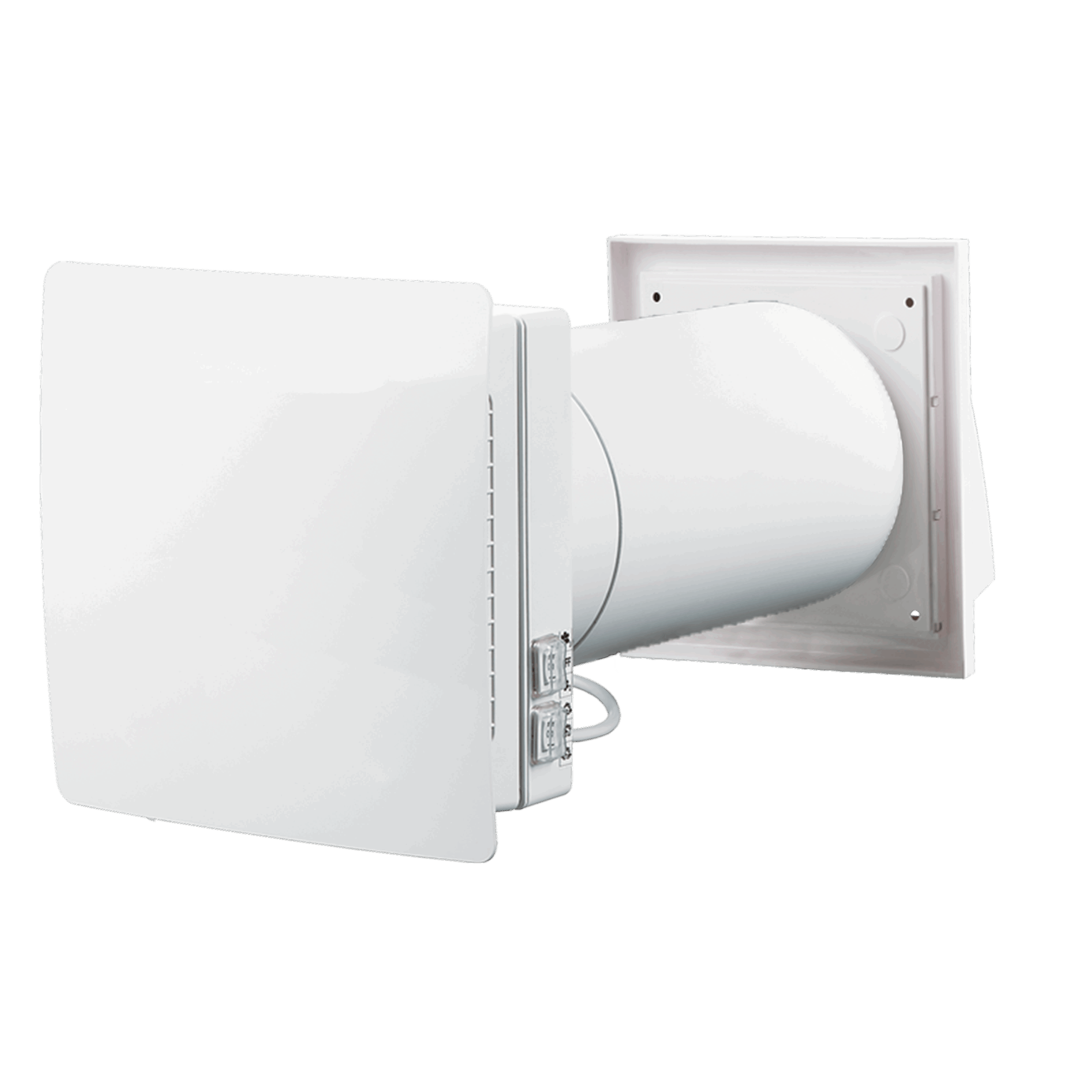
The DUKA One C6 consists of an indoor unit, which is divided into a motor section and an electronics section, a heat exchanger, air deflectors, filters, a storm shield and a telescopic tube. The indoor unit, containing the motor and electronics, is situated at the innermost part. The telescopic tube is mounted in the wall, housing the heat exchanger, filters and air deflectors. The filters remove dust and other particles from the air flowing through the unit. The air deflectors ensure the best possible distribution of the air. On the outside is the storm shield, which protects the unit from wind and rain.
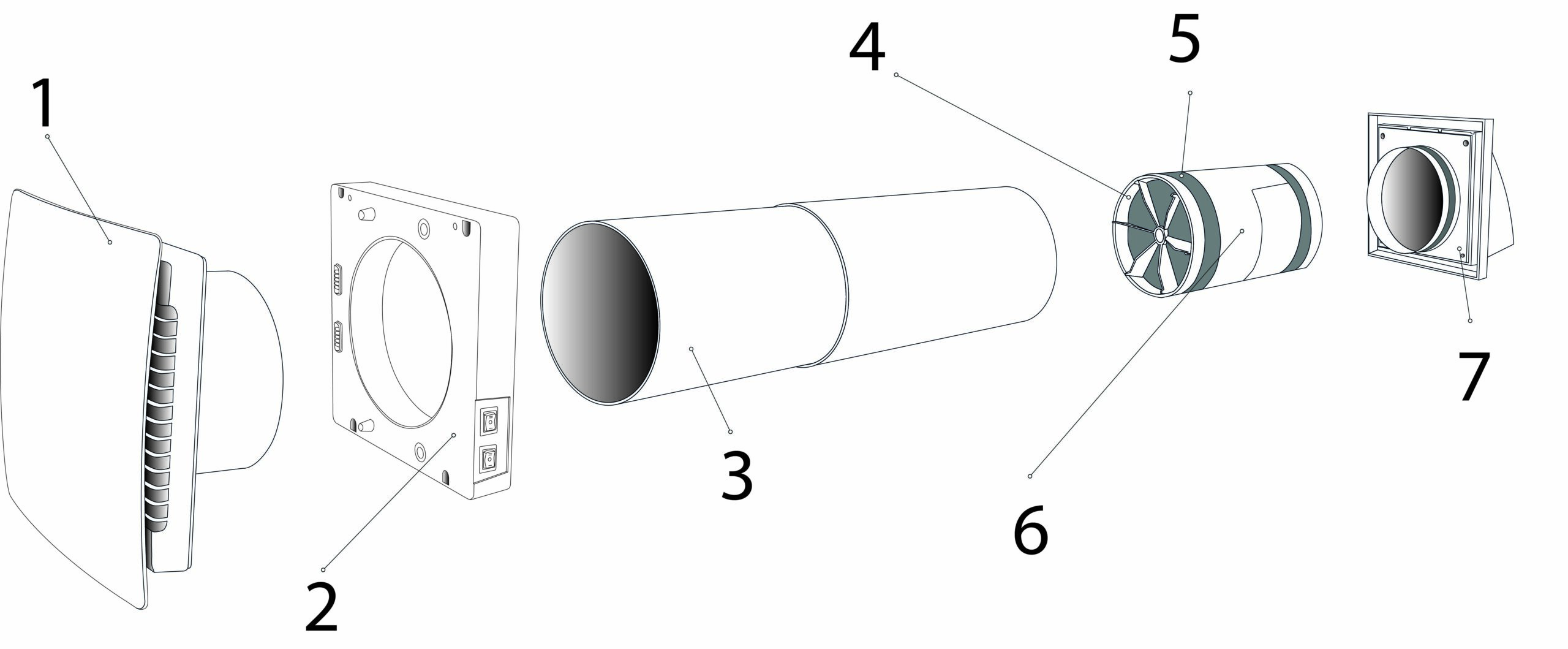
Front cover and engine
Front with 360-degree air intake and reversible motor
2 - 1TP7Electronic part
With panel for setting the
unit
3 – Telescope tube
Adjustable in length
4 – Filter
Must be inspected and cleaned every
quarter and alternate annually (also sit on the outside of the core)
5 - Air splitter
Distributes air evenly in the core
and provides higher
heat recovery efficiency (also sits on the outside of the core)
6 – Cores
Regaining warmth
7 – Windbreak
Available in multiple colours

Dimensions
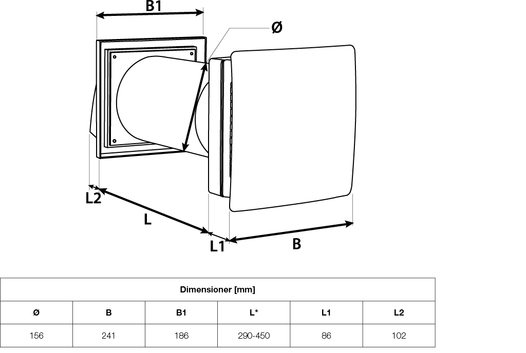
For lengths over 450 mm, 1000 mm extension tubes must be purchased separately.
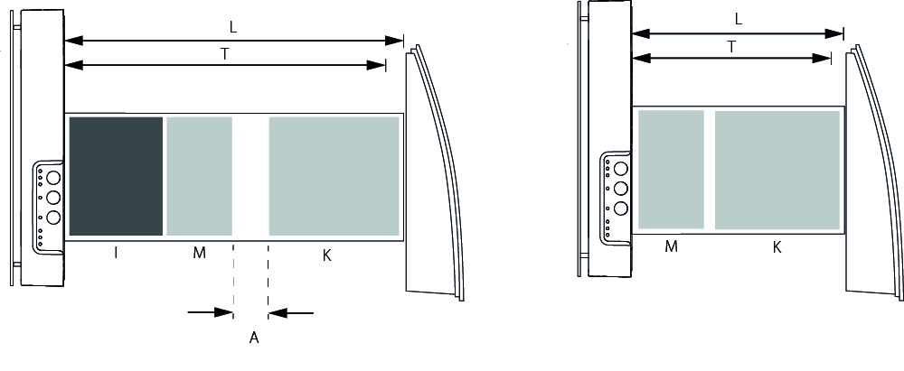
Minimum wall thickness for fitting DUKA One C6
If the wall thickness is below the minimum requirement, it is recommended to purchase DUKA One Spacer.
Position of the core in relation to the wall thickness:
Hole diameter (for mounting) 160-170 mm
Minimum wall thickness 290 mm
- K = Core
Mounting
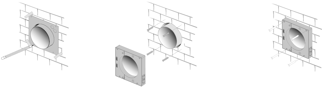
1 - Determine location and drill hole through the wall.
Before positioning the device, make sure to consider the following
Minimum distances to sidewall, ceiling and windows. Minimum distances
is shown in the drawing.
Don't forget to take into account the power supply for the device
when choosing a location.
For basement installation, it is recommended that the DUKA One unit
Positioned so that there is at least 0.3 - 0.5 m from the underside
of storm shield to terrain.
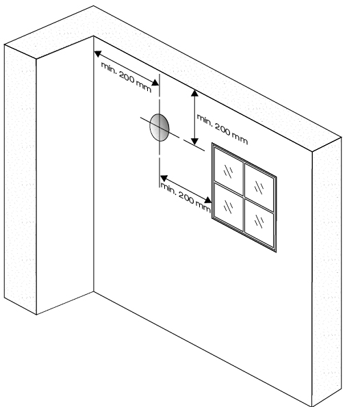
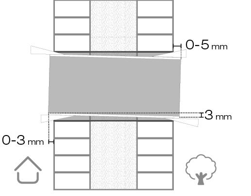
2 - Place the pipe in the hole and adjust the length to the wall thickness.
It is important that the pipe is installed with the prescribed drop of
3 mm, as it ensures that any condensation runs off
away from the electrical components of the device and out to
Storm shield.
For easy installation, it is recommended to use the included
polystyrene wedges.
The pipe must not protrude more than 3 mm on the inside and
5 mm on the outside.
3 – Remove the cover panel from the electronics to access the power connection.
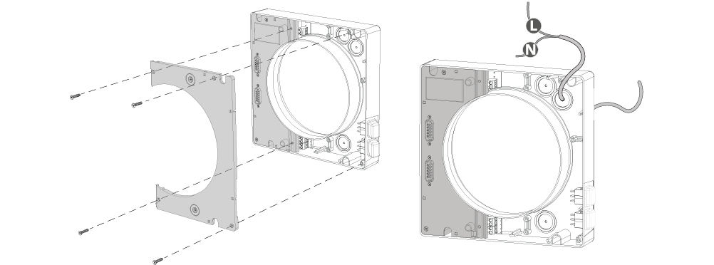
4 - Connect the electric cables according to the wiring diagram and route them as shown below. Remember to relieve the cables in the terminals.
Refit the cover plate once the electrical connection has been completed. See the section on El connection for further details. Refit the cover plate.
5 – Use the provided template for easy marking of the necessary drill holes for mounting and entry for concealed cable routing. Then, mount the unit’s electronic part using the screws provided.
6 – Mount the heat exchanger in the pipe with an air splitter and filter for each end. See the order on the drawing below.
Then place the motor part onto the electronics part.
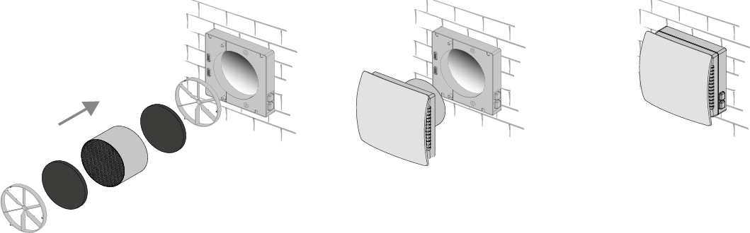
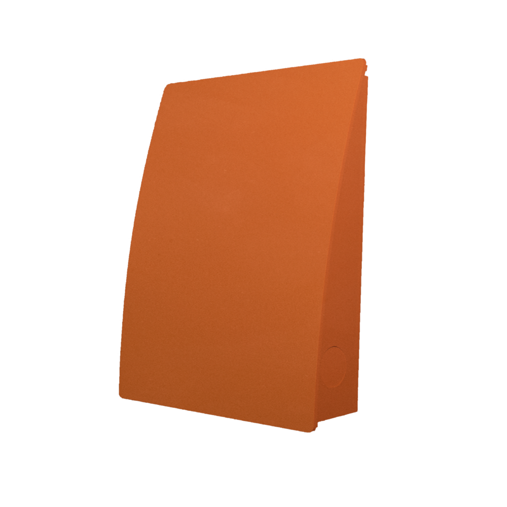
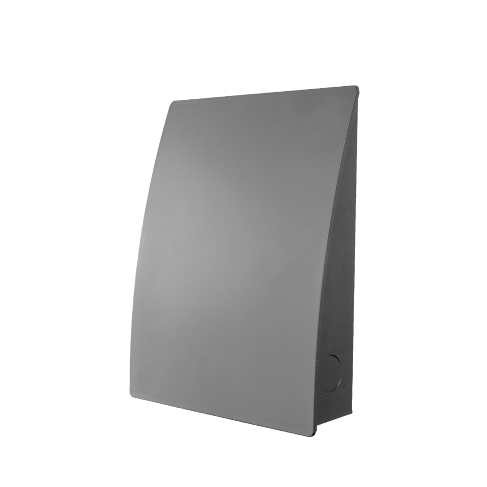
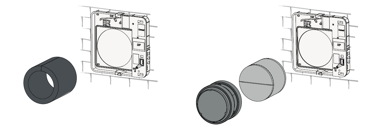
7 – Install the storm screen
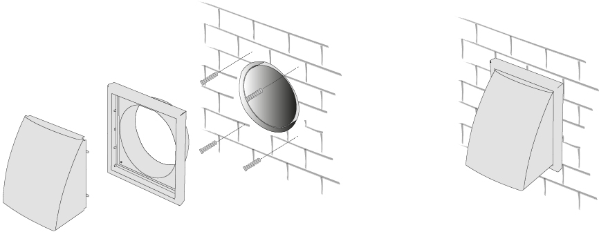
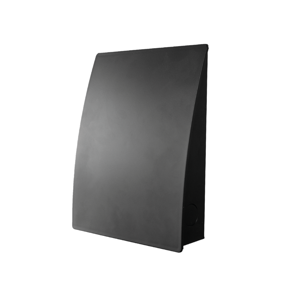
If you want the storm shield for your DUKA ONE in a different colour or design, you can replace it with one of the colours and/or models below.
El connection
ALL ELECTRICAL CONNECTIONS MUST BE CARRIED OUT BY AN AUTHORISED ELECTRICIAN.
CONNECTIONS THAT ARE MODIFIED OR ILLEGAL WILL INVALIDATE THE WARRANTY ON THE PRODUCT
REMOVED.
PLEASE NOTE: IT IS NOT LEGAL FOR PRIVATE INDIVIDUALS TO CARRY OUT THE FIXED INSTALLATION THEMSELVES.
SEE MORE AT THE DANISH SAFETY TECHNOLOGY AUTHORITY AT WWW.SIK.DK
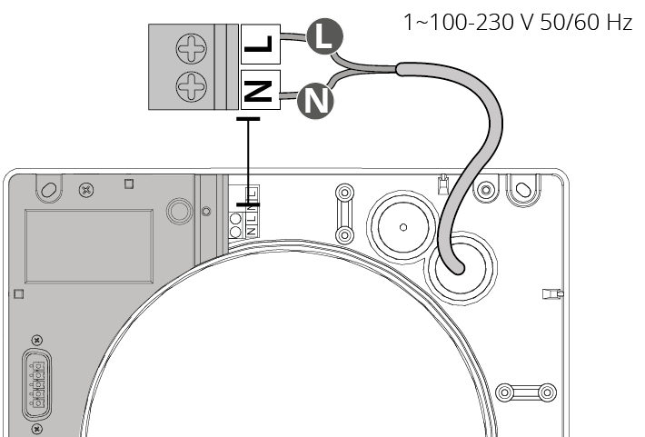
The device must be connected to a single phase AC 100-230 v / 50-60 Hz power supply.
The device must be connected to the mains via the terminal on the circuit board according to the electrical diagram below.
Pairing devices
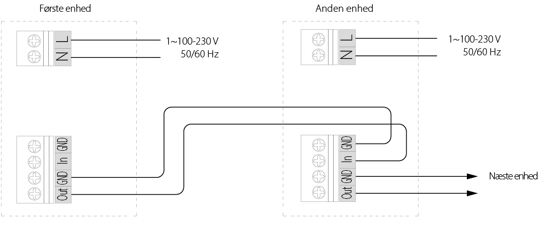
When connecting devices in a master/slave relationship, synchronous operation and balanced ventilation are achieved in the residence.
The units are connected via terminals on the electronic part as shown in the electrical diagram below.
A minimum of 0.25 mm² cable must be used to connect multiple units in series.
A power supply still needs to be connected to each individual unit.
El diagram for possible interconnection of devices
Settings and preferences
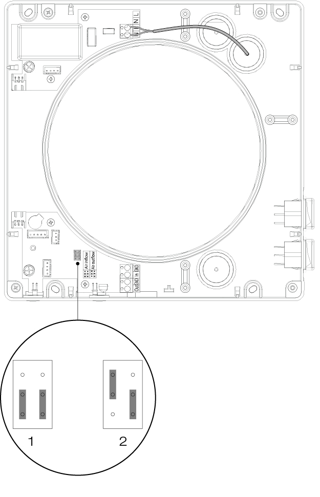
On the device, it can be set in which direction the device should drift in ventilation mode.
This is done via the terminal bridges as shown in the drawing.
- The unit in ventilation mode will be set to supply air
- The unit will be set to extraction in ventilation mode.
Operation
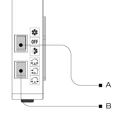
Operation of the unit via remote control is subordinate to the buttons on the internal display.
IF REMOTE CONTROL OPERATION IS DESIRED, THE BUTTONS ON THE SIDE OF THE UNIT MUST BE IN THE 0 POSITION.
Front cover features and control panel
By clicking the bottom, top or side of the front cover of the device, you can determine the blowing direction.
Note: The device is most effective when it is open on all sides.
NOTE: If the airflow needs to be shut off for safety reasons, the entire front must be closed and the unit switched off periodically.
See more under warranty conditions.
Operation
OPERATION ON THE SIDE OF THE UNIT TAKES PRIORITY. IF OPERATION WITH THE REMOTE CONTROL IS DESIRED, THE BUTTONS ON THE SIDE OF THE UNIT MUST BE SET TO THE 0 POSITION.
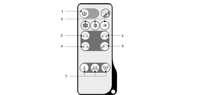
- On/standby
- Speed selection (from left: Step 3, Step 2, and Step 1)
- Natural ventilation (Do not use at outdoor temperatures below 10 degrees Celsius, or for extended periods)
- Ventilation – All connected units will constantly run in the set direction. See more under settings
- Blowing – All connected devices will constantly run on blowing
- Heat recovery – All interconnected units will switch between supply and extract, while recovering heat.
- Setting the humidity sensor. (From left: 45% RH, 55% RH and 65% RH)
Humidity settings
If the humidity is below the set value, the unit will drift in stage I.
If the humidity is at the set value, the unit will drift on stage II.
If the set value is exceeded, the unit will start operating in stage III.
The unit only measures humidity when moisture control is activated.
Maintenance
REMEMBER TO DISCONNECT POWER TO THE DEVICE BEFORE PERFORMING MAINTENANCE!
A DUKA One unit must be inspected and maintained at least every 3 months. There may be conditions where it is necessary to
Inspect your device more often, for example in a dusty, dirty or humid environment.
During maintenance, the core must be removed. The core is cleaned while the silencer and filters are cleaned or replaced.
Dismantle the casing parts and remove the air splitters, heat exchanger and filters from the ductwork.
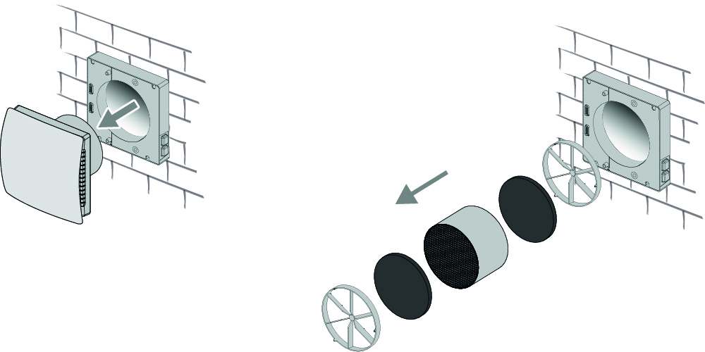
2 – Clean filters, heat exchanger, air diffusers and motor components.
Filters
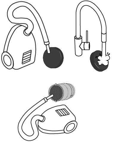
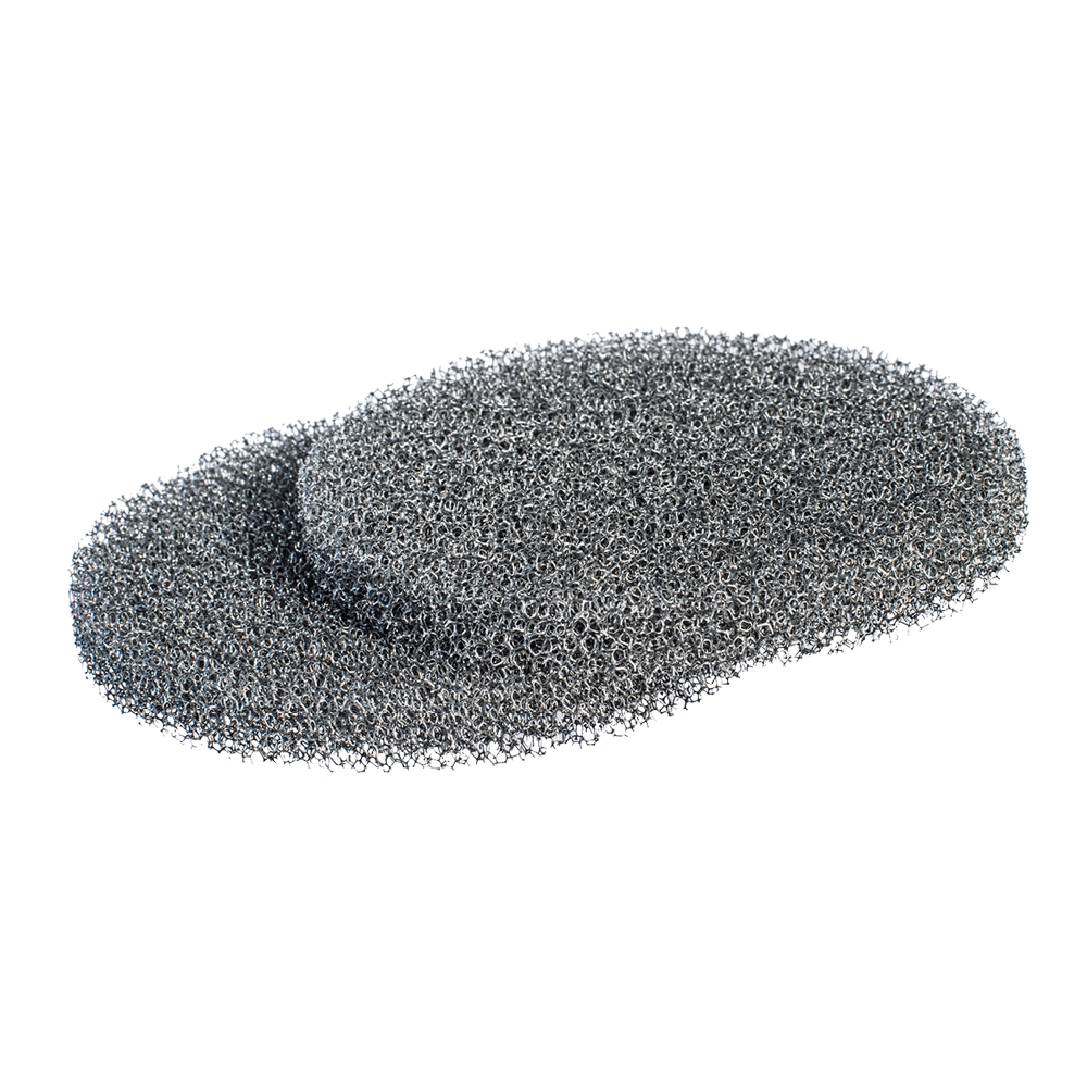
Depending on how clogged or worn the filters are, they can be washed or vacuumed, but a maximum of 3 times.
Allow the filters to dry before reinstalling them in the device.
Core
Organic particles from the unit's surroundings can settle in the ceramic core or on the fan, so it is important to clean these parts as well.
This is easiest done using a vacuum cleaner or with compressed air.
Cleaning engine parts and air splitters
Organic particles from the unit's surroundings can be deposited on the fan and air splitters.
This is why it is also important to clean these parts.
This is most easily done using a vacuum cleaner, compressed air or a lightly damp cloth. When using compressed air, the fan must be fixed so that it does not rotate uncontrollably.
Pipe routing
Clean the pipework with a damp cloth and mild detergent.
DUKA Clean can be used here.
Allow the pipework to dry before refitting the core and engine.
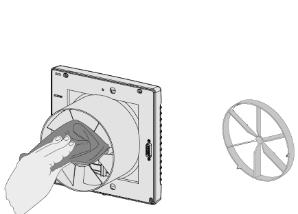
3 – Resetting the filter alarm
The maintenance alarm is reset by holding down the on/off button on the remote control for 10 seconds, after which the red LED will turn off.
Replacing the battery in the remote control
If the unit does not respond when the remote control is used,
Is it time to change the battery.
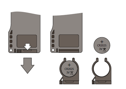
Pull the battery tray out of the remote control to change the battery.
CR 2025 battery
Insert the new battery into the compartment and push it back into the remote control.
The filters should be inspected at least every 3 months, where they should be cleaned or replaced depending on condition. At least once a year, the filters must be replaced with new original filters from DUKA Ventilation. It may occur that the unit is installed in an environment where a shorter maintenance interval than the minimum prescribed 3 months is required. For example, this could be in a dusty, dirty or humid environment.
For installations where there is a risk of mould, the device must be cleaned particularly thoroughly to completely remove dust and any fungal spores. It may be necessary to use a special cleaning agent. Failure to do so will invalidate the warranty on the product.
Replacing the battery in the remote control
If the unit does not respond when the remote control is used,
Is it time to change the battery.
Pull the battery tray out of the remote control to change the battery.
CR 2025 battery
Insert the new battery into the compartment and push it back into the remote control.
Faults and problem solving
Problem | Possible errors | Troubleshooting |
The device does not start | Power is not connected The motor is blocked or the fan meets resistance | Check that power is connected to the device and that the switch is switched on. Alternatively, ensure that the device is not connected incorrectly Check if the motor is blocked Clean the fan blades. Switch on the device |
Automatic circuit breaker switches on | Short circuit of the electrical network | Switch off the device and contact your dealer |
Low supply air temperature | The filters are clogged The ceramic core is iced up | Clean or replace filters Check the ceramic core for icing Switch off the device, remove the core and let the ice cream melt. |
Low air flow rate | The device is on the lowest setting
Filters, fan or ceramic core are clogged | Select higher speed steps
Clean or change filters
Clean fan and ceramic core |
High sound levels or vibrations | Clean fan Tighten screws | Clean the fan
Tighten screws |
Filter alarm button still lit after filter cleaning/change | Filter alarm reset has not been performed according to the instructions. | See the Maintenance section |
The device is running at full power, all speed LEDs are flashing and not responding to external signals | Humidity control in the DUKA One unit is switched on and activated | Switch off the DUKA One and set the humidity level or switch it off via DIP switch settings. See section Settings. |