



User manual
EL 500, EL 600, EL 700
Content
The 500, 600, and 700 series can be fitted with a damper. In that case, the length of the outlet pipe is increased by 14 mm.
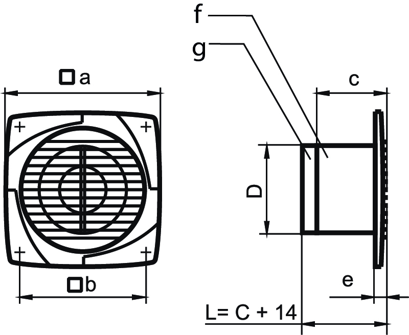
f – ventilator
g – backpressure damper
The box contains
1 extractor fan
1 piece installation manual
4 stk. skruer
Safety
All fans comply with the EU Low Voltage and EMC Directives as well as other EU norms and standards. Protection level in wet rooms:
IP44 500, 600, 700 series
1TP7 Electrical installations must always be carried out by a qualified electrician in accordance with the applicable regulations.
Fans installed in rooms exceeding 0-45° C, or in rooms with aggressive gases, are not permitted.
WARNING! Cleaning or other operations must not be carried out on the fan when it is in operation, as there is a risk of damaging the impeller.
Measures must be taken to prevent the backflow of gases into the room from other rooms containing gases.
Mounting
Important! Maintenance and connection work must only be carried out when the power is switched off. 1TP7 Electrical installation must always be carried out by a qualified electrician.
Wiring must only be carried out with at least 3 mm of stripped wire on all terminals.
Retning af luftstrømmen er angivet med pile på ventilatoren. EL 500 EL 600 EL 700 ventilatorer indsættes i ventilationskanalens åbning og monteres i loft eller væg med skruer. I tilfælde af at der ved montage af ventilatoren er mulighed for at få fingre i klemme i propellen, skal der tages modforanstaltninger for at undgå dette, evt. med udvendig rist, eller afskærmning.
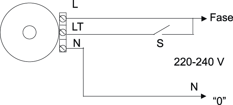
Figure 5-8 shows how fans are connected to the electricity supply.
For extractor fans without a switch, it is recommended to install an on/off switch on the fixed power supply.
Remove the protective cap thereafter. Route the power supply cable through the hole (3), strip the cable to a length of 7-8 mm for the terminal block (4) and secure with screws. Secure the cable using the clamp (2). Replace the protective cap.
The order in which the fan must be connected:
EL 500 EL 600 EL 700
Remove the protective grille and cover. Thread the power supply cable through the hole (3) (cut a small hole in the opening beforehand). Insert the power supply cable into the terminal block (4) and secure with screws. Place the power supply cable in the groove in the housing, which is secured in the locking brackets. Reattach the protective grille and cover.
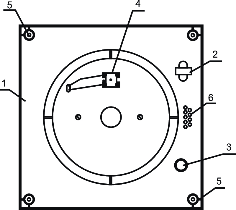
Figure 2
500, 600, 700 series with detachable cover and decorative grille.
- Cabinet
- Cable clips
- Cable holes
- Terminal block
- Holes for fan installation
- Cable entry
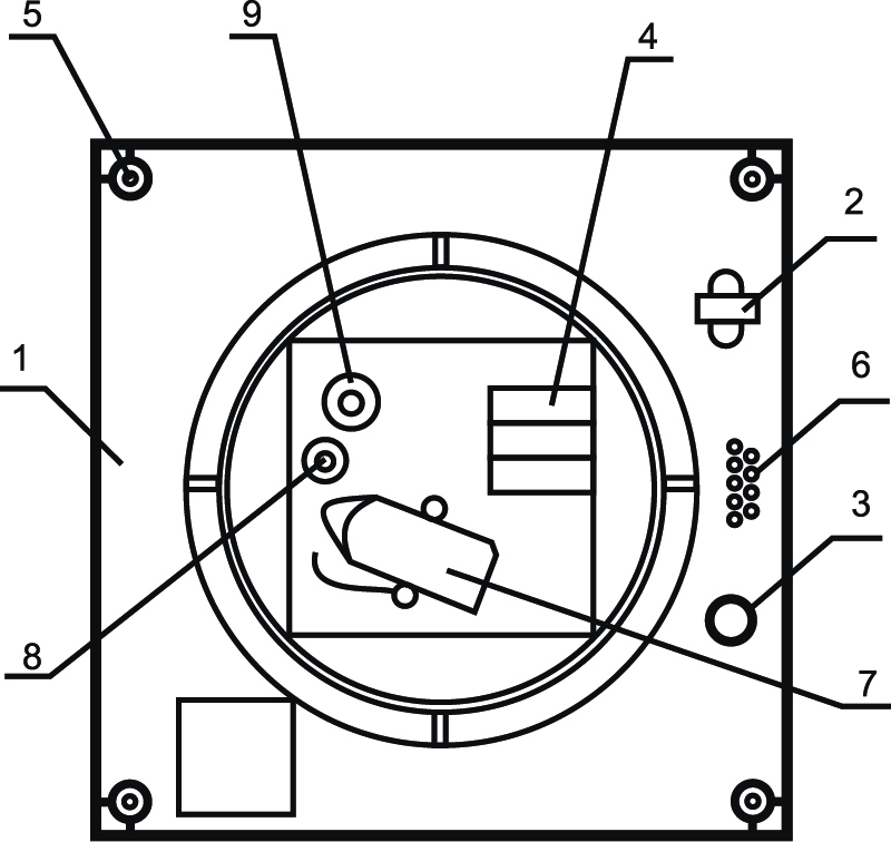
Figure 3
500, 600, 700 series with removable cover and decorative grille. Models: T, TH, S
- Cabinet
- Cable clips
- Cable holes
- Terminal block
- Holes for fan installation
- Cable entry
- Circuit breaker
- Timer
- Hygrometer
Figure 5
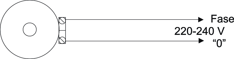
Figure 7
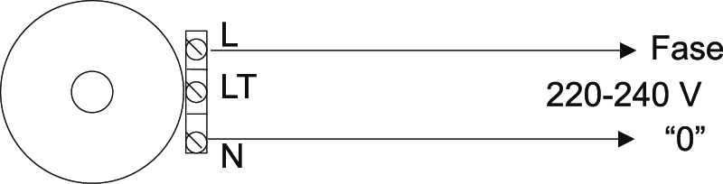
Figure 8
Diagrams fig. 5 and 7 for fans with a built-in isolator switch.
Phase 220-240 V
Figures 6 and 8 show the connection of fans without a built-in switch. S is an external switch (not included).
Fans with a timer function can be set between approximately 2 and 30 minutes. This can be adjusted using the timer button. Turning the button clockwise increases the number of minutes, whilst turning it anti-clockwise decreases the number of minutes. Fans fitted with humidity and timer controls start at the set level (50-90%). This can be set using the hygrometer button. Turning the button clockwise increases the % setting, whilst turning it anticlockwise decreases it.
IMPORTANT! The timer diagram is located under the front cover. The timer dial must not be adjusted unless the main switch is disconnected. The diagram in fig. 8 shows the connection for a lamp/light to the fan's timer via the light switch (S is an external switch, not incl.).
When the light is switched off, the fan runs for the number of minutes it is set to.
Timer and humidity sensor (TH)
The fan is controlled by a humidity sensor and a timer. The humidity sensor switches the fan on when the set level is exceeded. Can be adjusted between 60-90%. The timer activates the delay function for the set time when it receives a signal from the external switch. It can be set between 2 and 30 minutes.
(Factory setting 15 minutes)
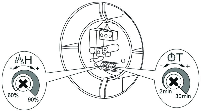
T: Adjusting the clock
Can be set from 2 to 30 minutes.
Increase: Turn the T knob clockwise (to the right)
Lower: Turn the T knob anti-clockwise (to the left)
H: Humidity adjustment
Can be adjusted from 60% to 90%.
Increase: To increase the humidity, turn the H knob clockwise (to the right)
Reduce: To lower the humidity, turn the H knob anti-clockwise (to the left)
Maintenance
Disconnect the power before commencing cleaning. The fan should be cleaned at least twice a year under normal use, or more often if necessary. The fan is cleaned with a damp cloth and washing-up liquid, after which it is wiped with a dry cloth.
Never use solvent!
Guarantee
DUKA Ventilation provides a 36-month warranty on the fan from the date the fan is sold through retail, provided that the requirements for installation and maintenance are complied with and it is installed by an authorised electrical contractor.
If the date of sale of the fan can be called into question, the warranty is valid from the date of manufacture.
Should any operational faults occur within the warranty period due to manufacturing defects, the fan will be repaired or replaced by DUKA Ventilation.