User manual
SmartFan Wi-Fi
Extractor fan with Wi-Fi control
Content
DUKA SMARTFAN
This user manual contains technical descriptions and data, an installation guide, and servicing information for the DUKA SmartFan ventilator.
Please read these instructions thoroughly before installation and use.
The installation must comply with DS 447.
DUKA Ventilation reserves the right to make changes to the technical data, design and configuration of the product in order to incorporate the latest technical developments. The most up-to-date documentation can always be found at www.dukaventilation.dk.
Important before installation
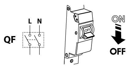
Before installation, service and maintenance, the power supply to the fan must be disconnected.
The fan is intended for fixed installation and must therefore be connected by an authorised installer.
The single-phase electricity grid must comply with applicable electrical codes and standards.
The installation must be equipped with an automatic circuit breaker.
The device must be connected to the mains power supply via a miniature circuit breaker (MCB) integrated into the fixed wiring.
Check the unit for visible damage to the fan and casing before starting installation. The internal parts of the casing must be free of foreign bodies that could damage the fan components.
Avoid applying pressure to the fan during installation. Damage to the casing can lead to motor failure and noisy operation. Incorrect use and unauthorised modifications are not permitted and will invalidate the warranty.
Ensure that smoke, carbon monoxide and other combustion gases cannot enter the room through open flue ways or other fire safety systems. Adequate air supply must be ensured for proper combustion and extraction of gases through the chimney to prevent downdraughts. Conveyed air must not contain dust or other solid material with impurities, sticky substances or fibrous materials.
Must not be used in explosive or hazardous environments with alcohol, fuel, spray agents, etc.
Air inlets and outlets must not be blocked to ensure optimal airflow.
Warranty terms
DUKA Ventilation offers a 24-month warranty from the date of purchase, in accordance with the Sale of Goods Act.
In addition, DUKA Ventilation offers a further 36-month warranty on top of the right to make a claim, provided that all the obligations and instructions set out regarding use, installation, storage, transport and maintenance are complied with.
In the event of a complaint, please present your receipt and, if applicable, the installation invoice from the electrician. The fan must be used as described in the user manual.
The warranty does NOT cover:
• Routine maintenance.
• Fitting and removing the fan.
• Fan installation.
In the event of a complaint, please fill in our complaint form at: www.dukaventilation.dk/reklamation.
DUKA Ventilation cannot be held liable for warranty obligations carried out without prior agreement with us/our dealer.
The warranty does not cover the following cases:
• If the fan has not been installed in accordance with the installation instructions, this also includes parts within the fan.
• If all electrical connections have not been made correctly and in accordance with the manual.
• If the fan has not been properly serviced at regular intervals.
• If there is visible damage to the fan housing or to any parts inside the housing.
• If any technical components have been added to or removed from the fan.
• In the event of incorrect use of the fan.
• Deviation from the user manual.
• Connection to an electricity supply other than that described in the manual, i.e. the standard mains supply.
• Fluctuations in the mains voltage.
• Unauthorised repairs to the fan.
• If the warranty has expired.
• Derogation from transport rules.
• Deviation from storage regulations.
• Fan faults caused by Force Majeure. (fire, flood, earthquake, rough handling)
• If a receipt for the purchase cannot be provided.
Transport and storage
Store the fan in its original packaging in a dry, well-ventilated room at a temperature of between +5 ºC and +40 ºC and a relative humidity of up to 70 %.
The storage room must not contain aggressive and chemical vapours.
The fan must not be subjected to continuous pressure and load.
PLEASE NOTE: All electrical work must be carried out by a registered electrician.
The fan may be transported by any vehicle, provided that it is protected against damage during transport and the elements.
The fan must be protected against knocks and impacts throughout the entire journey
Contents of the box
Ventilator 1 pc.
100 mm pipe spigot 1 pc.
125 mm spigot pipe 1 pc.
Screws and rawlplugs 4 pcs.
Technical data
The DUKA Smart Fan extractor is an axial fan made of high-quality plastic designed for extraction.
Voltage [V] 100–240
Frequency [Hz] 50–60
Max. Power [W] 6.0
Amperes [A] 0.07
RPM [min⁻¹] 2200
Max. air volume [m³/h] 133
IP rating IP44
Stud diameter | Speed and speed | Max current [W] | Ampere [A] | Air volume [m3/h] | Revolutions [min-1] | Sound level at 3 m [dBA] |
Ø100 mm | 24 hours | 1,6 | 0,02 | 33 | 950 | 17 |
Silence | 2,9 | 0,04 | 72 | 1650 | 21 | |
Hi | 5,6 | 0,06 | 106 | 2150 | 31 | |
Ø125 mm | 24 hours | 1,7 | 0,03 | 40 | 850 | 17 |
Silence | 3,0 | 0,04 | 83 | 1350 | 22 | |
Hi | 6,0 | 0,07 | 133 | 2200 | 32 |
Ventilator features:
• Moisture sensor
• Ventilation function
• Delayed startup
• Early retirement period
• Speed camera
• Intermittent ventilation
• External contact
IP44 rating protects against access to hazardous parts and the device against splashing water.
The fan can be used in rooms with a room temperature from +1 ºC to +40 ºC
The fan is classified as a Class II electrical appliance.
Technical data
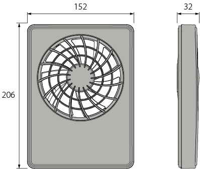
Dimensions
Standby: The fan is out of order. Operation is activated upon start-up of 24-hour mode, upon a signal from the temperature/humidity sensor or activation of an external switch.
24-hour mode: The fan runs at a low speed, ensuring constant background ventilation around the clock. If the fan is activated via the temperature/humidity sensor or an external switch, the operation switches to Silent or Max programme.
Silent The fan starts between operations when the LT and LI terminals are activated. The speed can be adjusted in the DUKA Smart App.
Max. speed: Activated by temperature/humidity sensor or by Boost Mode.
Assembly
1. In the case of vertical installation, the fan must be protected against the accumulation of water and condensation in the ductwork. Installation directly with a vertical air discharge is not permitted. The installation must be carried out in accordance with Danish Standards.
2. Disconnect all power supplies before carrying out the installation.

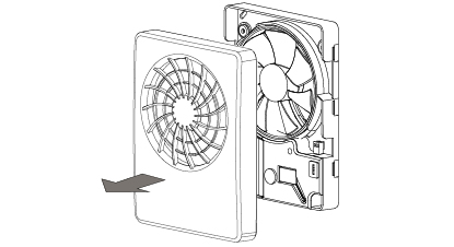
3. Remove the front panel of the extractor fan.
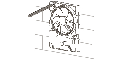
4. Mark the holes for mounting and cable routing.
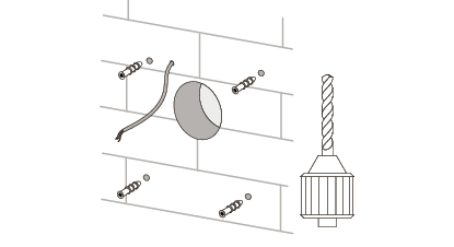
5. Route the power cable to the ventilation duct. Drill holes for mounting and fit wall plugs.
6. Secure the fan to the wall with the screws.
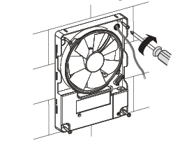
7. Remove the cover to access the terminal block and connect the power cable to the fan according to the electrical diagram (see below). Reassemble the fan in reverse order.
8. Switch on the power at the isolator switch. Choose whether the fan should ventilate on speed 1 or speed 2.
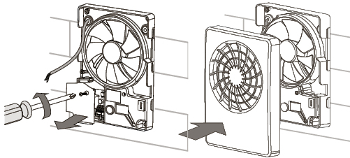
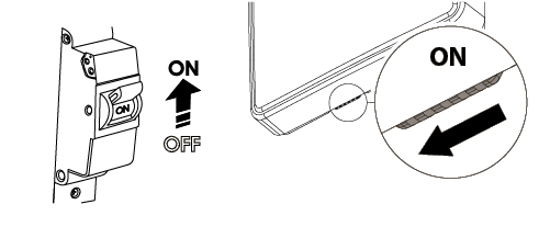
El diagram
Connection to power supply
The fan must be connected to a single-phase AC 100-240 V / 50 (60) Hz power supply.
Designation of the terminal block
L Phase
N: Rubbish
LT Fan speed control
LI: External contact output
SK: Speed change contact
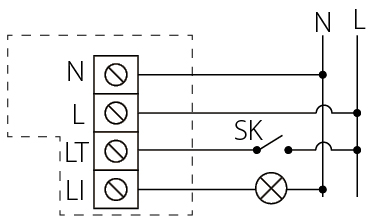
Operating the fan
The fan is operated via the DUKA Smart App. The latest version of the DUKA Smart App can be found in the Play Store for
Android phones and the App Store for iOS phones.
Note: Wi-Fi setup requires a direct connection to the router with a 2.4 GHz network

Android:
https://play.google.com/store/apps/details?id=com.embarcadero.DukaOneWIFI&hl=da
Apple
https://apps.apple.com/hr/app/duka-smart-app/id1354423127
Set up device in app
Setup options
The initial startup of the DUKA Smart App grants access to the Device List. Here, users will have the option to connect the device locally or to a home network, from which one or more devices can be accessed and controlled.
Local connection
When establishing a local connection to the device, it is only possible to control the device when you are connected to the fan's fan ID network. If the connection is lost or disconnected, it is necessary to re-establish it.
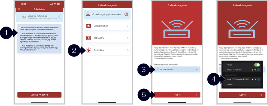
To connect to the fan's local network, do the following:
1. Tap local connection under the device list
2. Select SmartFan
3. Select network device search
4. Select the network you wish to connect to. The fan ID number can be seen under the front cover by the rubber flap. The default code is 11111111 (eight 1s).
5. Press Next
A local connection has now been established, and it is possible to control the device and change operating settings. For more on this, see
the control panel.
Connect the extractor fan to the home network
By connecting the device to the home network, it becomes possible to connect multiple devices in the app. Here they can be named and controlled individually.
To control the device via the app on your home network, you must log in to the app. If you do not have an account, a new one can be created within the app.
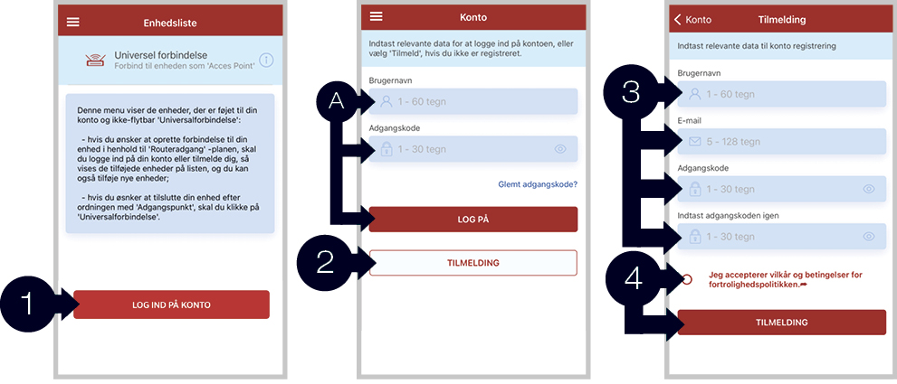
Connect the fan to the home network.
1. Tap LOG IN TO ACCOUNT on the device list
A. If you already have an account, enter your username and password and go to step 5
B. Don't you have a user, then go to step 2
2. Press REGISTER
3. Enter desired username, email address and password
4. Tick the terms and conditions box before creating a user account
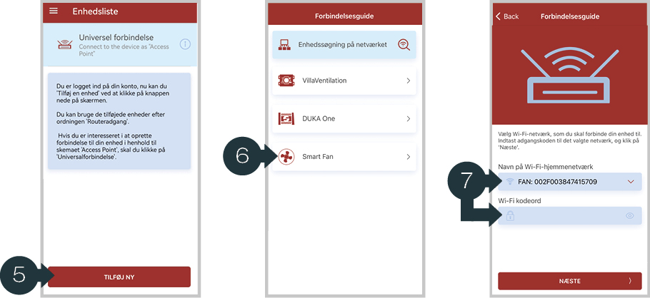
5. Press ADD NEW
6. Tap SmartFan
7. Select the network you want to connect the fan to and enter the password. Press NEXT.
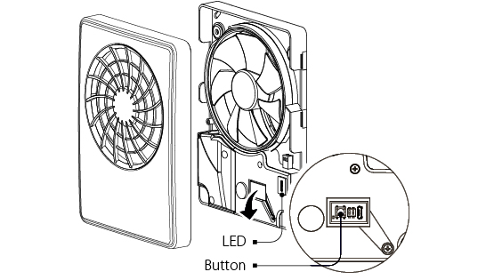
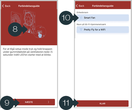
8. Hold down the setup button on the fan for about 5 seconds until the LED indicator flashes blue
9. Tap NEXT
10. Give the unit a name
11. Press READY
Operating the fan
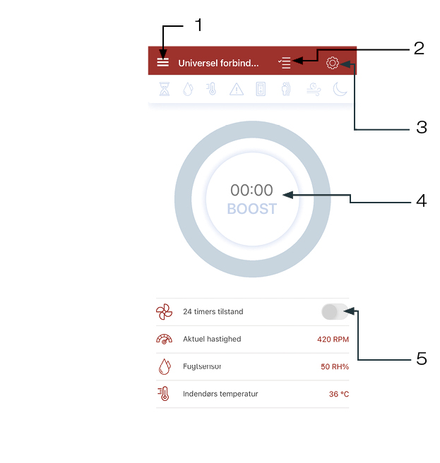
1 – Main menu
2 – List of units
3 – Settings
4 – Boost function
5 – Activation of 24-hour mode
Indicator explanation

Boost or overrun is activated

Humidity sensor is activated

Temperature sensor activated

Warning indicator (battery needs replacing)
External contact is enabled

Motion sensor is activated (this model does not have a motion sensor)

Ventilation mode is activated

Do not disturb is enabled

24-hour mode is enabled

Shows the motor speed

Shows current moisture level

Showing current temperature
DUKA Smart App main menu
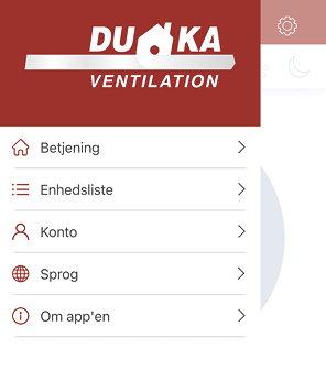
The main menu is opened by pressing ☰. The main menu is divided into various menus from which changes can be made.
Operation
From the control tab it is possible to control a connected device.
Unity List
In the ’Enhedslisten’ tab, there is an overview of the units that are connected to the account.
This is also where you add and remove devices from your list, as well as change device names.
Account
Here you can do various things regarding your account. Change password, associated email, log out or delete the account.
Language
Here it is possible to set which language you want for the app.
About the app
Read more about our Privacy Policy Terms and Conditions.
Ventilator settings
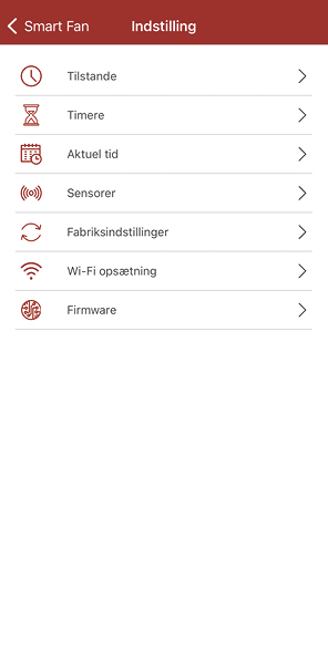
Conditions
Here, silent and max ventilation speeds can be set, and 24-hour mode and the ventilation interval can be activated. 24-hour mode ensures constant background ventilation at the silent level. The ventilation interval allows for ventilation every 12 hours if the fan has not been activated for 24 hours.
Timers
Here, delayed start as well as run-on time and boost time interval can be set.
Current time
Set current time for the fan. Can be synchronised with mobile device.
Sensors
Settings for the temperature and humidity sensor and for activation via an external switch can be made here.
The temperature sensor can be set between 18 and 36 ºC. Can be used for heat transfer.
External contact can be activated if you wish to operate the fan via an external switch.
The humidity sensor can be activated and set to Auto (intelligent humidity control) or Manual (can be set between 40 and 80%)
Factory settings
Restore the device to factory settings.
Wi-Fi setup
Manually connect the device to network.
Firmware
View the firmware version of the device.
Technical maintenance
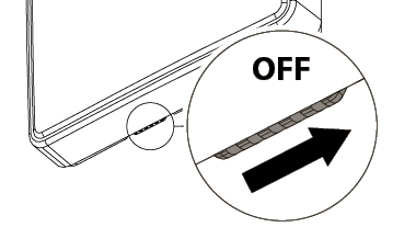
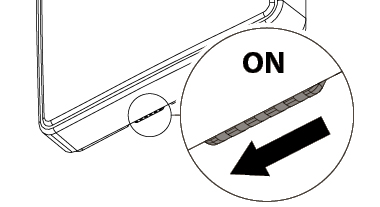
1. Switch on the extractor fan's safety switch.
The ventilator operation is locked hereafter.
Warning! The safety switch does not cut off the power to the fan.
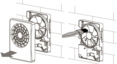
2. Remove the front panel.
Clean the fan blades with a dry, soft cloth or brush.
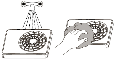
3. Wash the front panel under running water. Wipe the front until it is dry again.
4. Turn the safety switch back off. Activate the fan in the app.
Replace battery
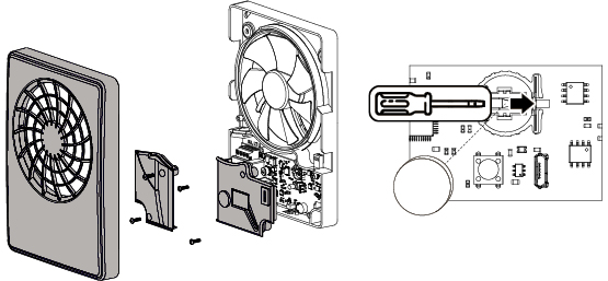
If the battery level is low or flat, a warning is shown in the app. If the warning is active, the battery must be replaced.
When changing the battery, the power to the fan must be disconnected. Remove the front panel and the cover for the control panel.
Change the battery (battery type CR1220) on the control panel.
Assemble the fan in reverse order.
Reset the fan (LED Description)
To restore factory settings, press and hold the button for 14 seconds until the LED starts flashing red and the fan beeps.
Access to the button
The LED has the following states:
Doesn't light up: Normal operation of the fan
Glows blue: Warning about transition to setup mode
Flashing blue: The device is in setup mode
Glows red: Warning to restore factory settings or to exit setup mode.
Flashing red: The fan has been restored to factory settings.