


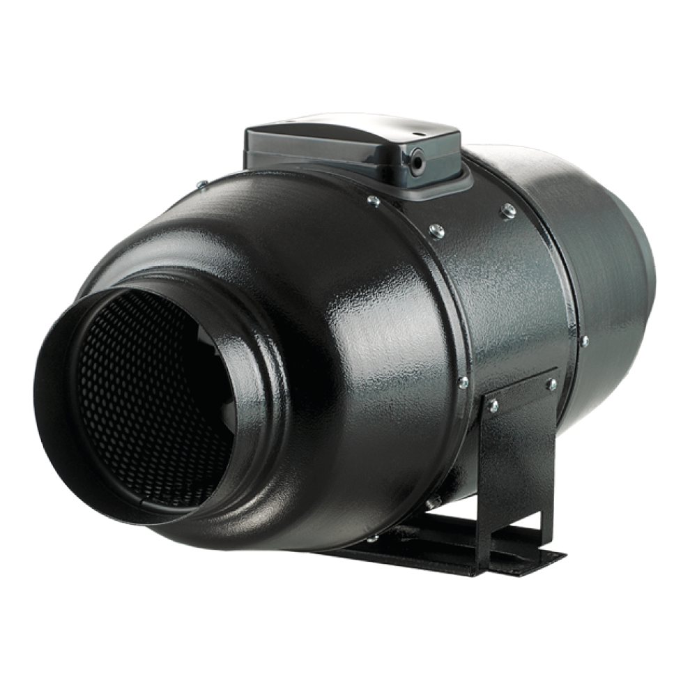
CHANNEL VENTILATOR WITH
LYDISOLATED OFFICE
100 TT Silent / 125 TT Silent / 160 TT Silent
User guide
Content
This user guide is the primary operational document for technical staff, maintenance staff, and operational staff.
The guide contains information about the use, technical characteristics, operating principle, design and installation of TT Silent and all variants of the product.
Technical staff and maintenance personnel must have theoretical and practical training in ventilation systems and be able to work in accordance with the regulations on occupational safety as well as the building regulations and standards applicable in the country concerned.
FOLLOW THE USER GUIDE REQUIREMENTS TO ENSURE LONG-TERM AND PROBLEM-FREE OPERATION OF THE UNIT.
SAFETY REQUIREMENTS
This device is not intended for use by persons, including children, with reduced physical, sensory or mental abilities or lacking experience and knowledge, unless they are supervised or have been instructed in the use of the device by a person responsible for their safety.
Children must be supervised to ensure that they do not play with the device.
The device must be used by children aged 8 and above, and by persons with reduced physical, sensory or mental abilities or lacking experience and knowledge, if they are supervised or have been instructed in the safe use of the device and understand the associated hazards.
Cleaning and maintenance performed by the user must not be performed by children without supervision.
Children must not play with the device.
Connection to the electrical network must be made via a circuit breaker built into the fixed installation in accordance with the regulations for the execution of electrical installations. The circuit breaker must have a contact distance on all poles that allows for complete disconnection under conditions corresponding to category III overvoltage.
If the power cable is damaged, it must be replaced by the manufacturer, its service representative or persons with equivalent qualifications to avoid a safety risk.
WARNING: To avoid a safety risk from accidental resetting of the overheating protection, the device must not be powered via an external switch, such as a timer, or connected to a power circuit that the utility company regularly turns on and off.
Check that the device is disconnected from the power supply before removing the protective grille.
Precautions must be taken to prevent the backflow of flue gases into the room from open exhaust vents from gas appliances or other fuel-fired appliances.
The unit may affect the safe operation of appliances that burn gas or other fuels, including appliances in other rooms, due to the backflow of combustion gases. These gases can cause carbon monoxide poisoning. After installation, a qualified professional must check the operation of gas appliances with exhaust systems to ensure that no backflow of combustion gases occurs.
All work described in this guide must only be carried out by qualified personnel with the necessary training and qualifications for the installation, electrical connection and maintenance of ventilation units.
Do not attempt to install the product yourself, connect it to the mains power or perform maintenance. This is dangerous and cannot be carried out without special professional knowledge.
Disconnect the power supply before any work is performed on the device.
During installation and operation, all requirements in the user manual as well as all applicable local and national building regulations, electrical regulations and technical standards and standards must be observed.
Disrupt the power supply to the device before connection, servicing, maintenance, and repair.
The unit may only be connected to the mains by a qualified electrician with permission to work on electrical installations up to 1000 V, after this user manual has been carefully read.
Before installation, check that the fan wheel, cabinet, and grille are free of visible damage. The interior of the cabinet must be free of foreign objects that could damage the fan wheel blades.
Avoid compressing the cabinet during assembly. Deformation of the cabinet can block the motor and cause loud noise.
Incorrect use and unauthorized modifications of the device are not allowed.
The transported air must not contain dust or other solid impurities, sticky substances or fibrous materials.
Do not use the device in a hazardous or explosive environment that contains alcohol, gasoline, insecticides, or the like.
The intake and exhaust openings must not be closed or blocked, as this prevents an effective airflow.
Do not sit on the device and do not place objects on it.
The information in this user guide was correct at the time of document preparation.
The company reserves the right to change the technical characteristics, design or configuration of the products at any time in order to incorporate the latest technological developments.
Never touch the device with wet or damp hands.
Never touch the device when you are barefoot.
READ THE RELEVANT USER GUIDELINES BEFORE FURTHER EXTERNAL DEVICES ARE INSTALLED.
The product must be disposed of separately after the end of its intended life.
THE UNIT MUST NOT BE DISPOSED OF AS UNRECIPIENT HOUSEHOLD WASTE.
CONTENTS OF THE PACKAGE
Fan – 1 piece.
Raws screws with rawlplugs – 4 pieces.
Plastic screwdriver (only models with timer) – 1 piece.
User guide – 1 copy.
Packaging box – 1 piece.
OPERATIONAL INSTRUCTIONS
The fan is designed for single-phase alternating current: 220-240 V / 50 Hz or 220 V / 60 Hz.
The fan is designed for continuous operation.
The direction of air movement in the system must follow the arrow on the fan's casing.
The device is an electrical appliance in class II.
The protection level against access to dangerous parts and penetrating water is IPX4.
The fan is designed for an ambient temperature from +1 °C to +40 °C.
Supply voltage [V/Hz] The air temperature transported [°C]
220-240/50 -25…+60
220/60 -25…+40
To comply with the ErP 2018 regulation, a local demand control and a speed regulator must be used.
SHORT DESCRIPTION
ProThe duct is a channel fan with mixed airflow for the supply system, as well as systems with inlet and exhaust in rooms.
The fan is designed for air ducts with a diameter of 100, 125 or 200 mm.
An external control unit can be connected to the fan.
The design is continuously improved. Therefore, certain models may differ slightly from those described in this guide.
TECHNICAL DATA
ProThe duct described here is a channel fan with mixed airflow for supply or extraction in rooms that are heated in winter. The fan is designed to be connected to air ducts with a diameter of 100, 125 or 160 mm.
The fan has a motor with two speeds.
An external control unit can be connected to the fan.
The fan's design is continuously improved. Therefore, certain models may differ slightly from those described in this guide.
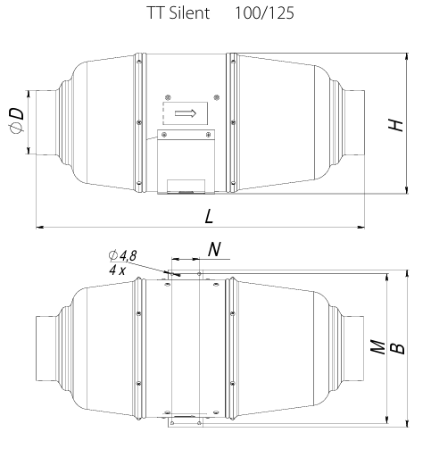
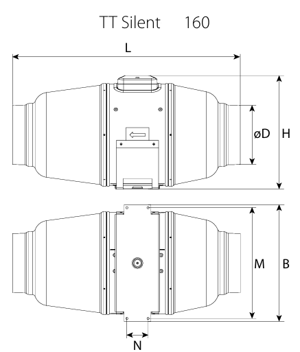
Dimensioned drawing
Model name | Ø D | B | H | L | M | N |
100 TT Silent | 98 | 243 | 220 | 505 | 231 | 42 |
125 TT Silent | 123 | 243 | 220 | 474 | 231 | 42 |
160 TT Silent | 157 | 273 | 263 | 580 | 231 | 44 |
INSTALLATION AND ASSEMBLY
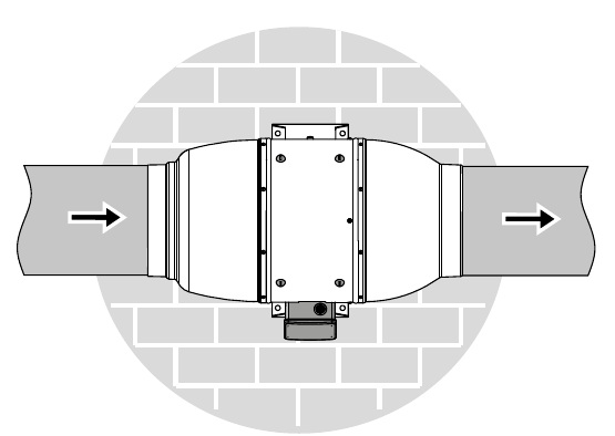
The fan can be mounted horizontally or vertically on the floor, wall or ceiling.
During assembly, ensure extra protection against penetrating water:
• When mounting vertically, a protective cap must be installed at the top.
• Connect an air duct on both sides of the fan regardless of the mounting position.
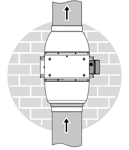
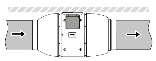
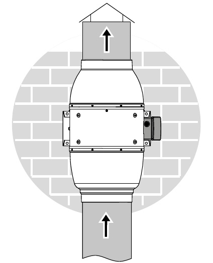
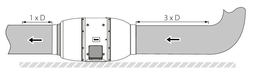
INSTALLATION
1. Mark the holes for attaching the fan and the power cable.
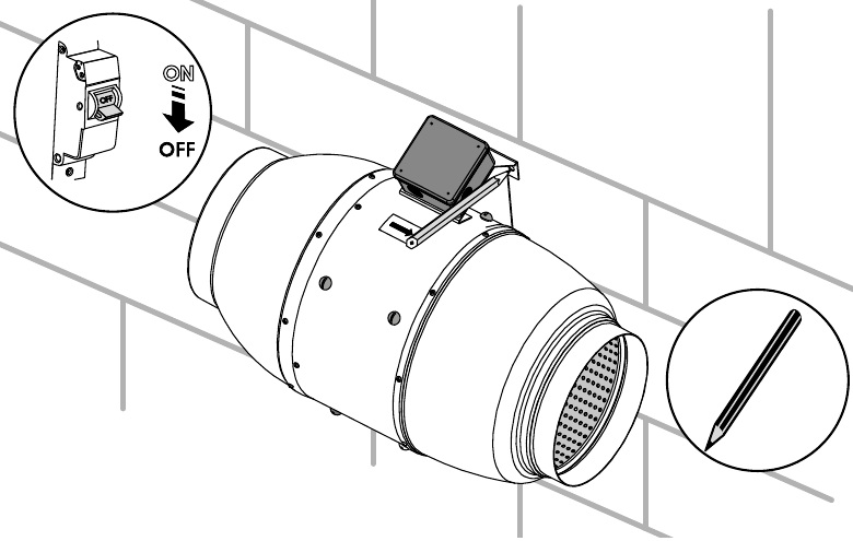
2. Before connecting the power cable to the ventilation opening, drill the mounting holes and insert the rawlplugs.
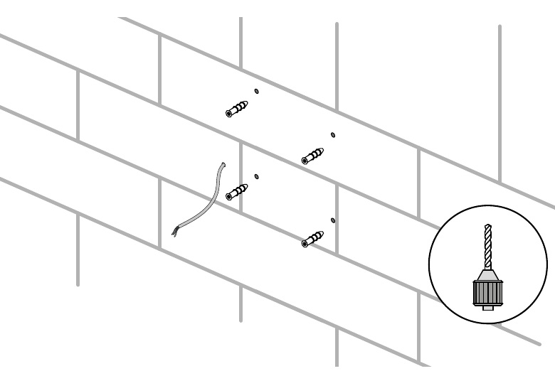
3. Attach the fan with the screws.
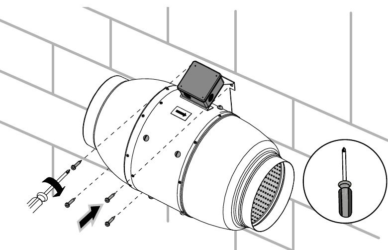
4. Connect an air duct on both sides of the fan regardless of the mounting position.
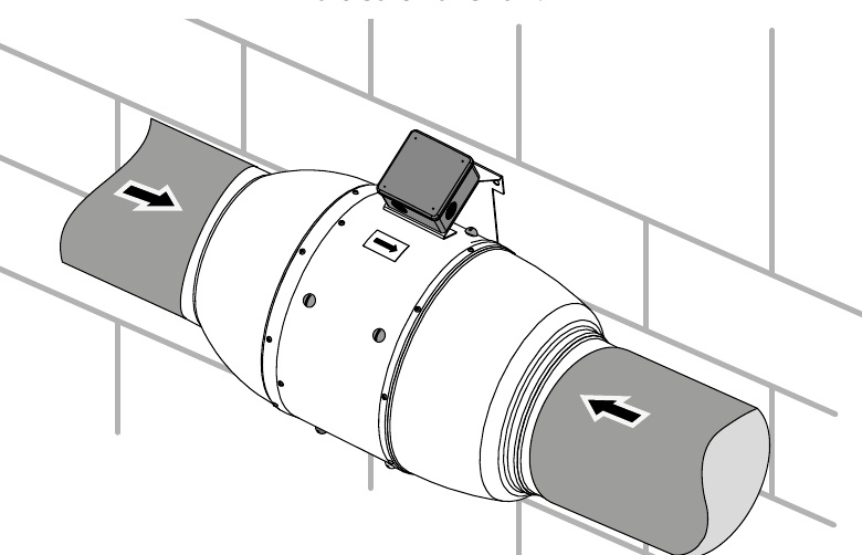
5. Remove the clamp bar cover.
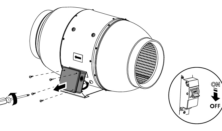
6. Prepare the hole.
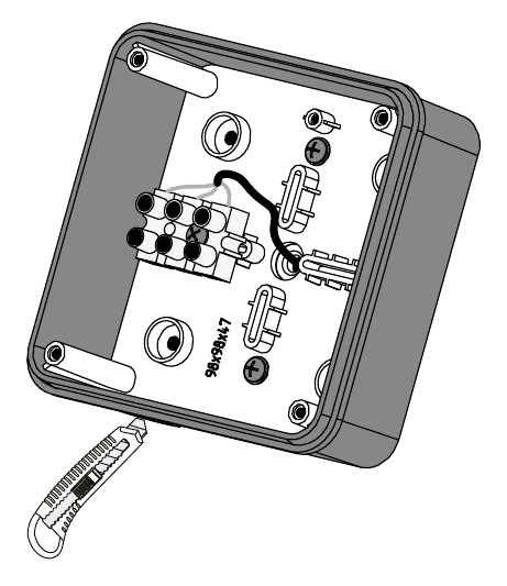
7. Connect the power cable leads to the terminal block.
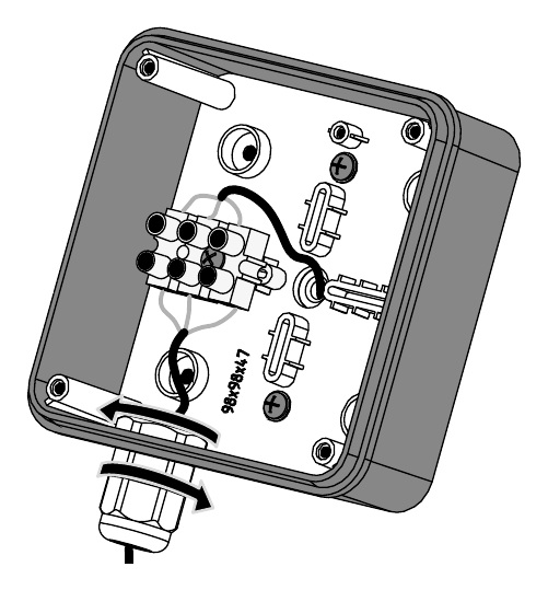
8. Assemble the fan in reverse order.
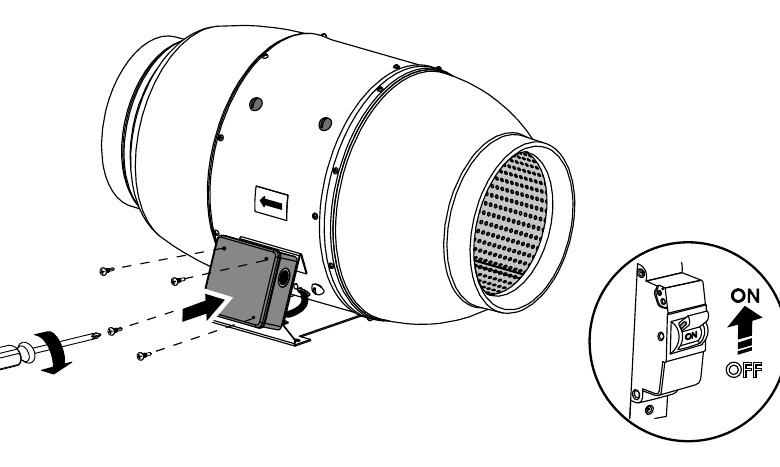
CONNECTION TO THE ELECTRICITY NETWORK
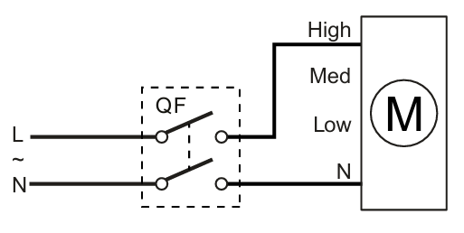
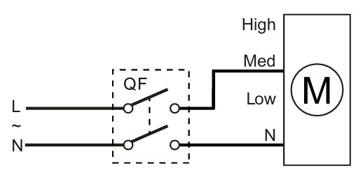
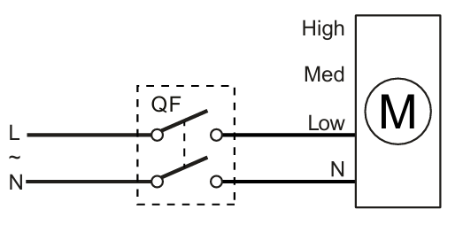
Terminal designations in the electrical diagrams
L phase
N – zero
LT – control cable for hours
ST – external switch
L1 – clamp for lowest speed
L2 – clamp for highest speed
Low – clamp for lowest speed
With – clamp for medium speed
High – clamp for highest speed
QF – external speed switch
X – crimp sequence
Indicator markings in the illustrations: ON = on, OFF = off.
DO NOT USE A METAL SCREWDRIVER, KNIFE, OR SIMILAR FOR ADJUSTING, AS IT CAN DAMAGE THE PRINT CARD.
High speed
Average speed
Low speed
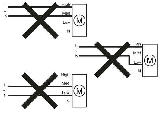
Not allowed
FUNCTION OF ELECTRONICS
The fan speed on models without an option can be adjusted using voltage regulation or with thyristor regulators. The speed regulator is purchased separately.
Warning! When adjusting the voltage, you must ensure that no unusual noise or vibrations occur at reduced engine speed.
The motor current can exceed the nominal current during voltage regulation.
The fan is equipped with a thermal switch without automatic reconnection.
This is how the thermal relay is reconnected:
• Disconnect the power supply.
• Find and remedy the cause of the overheating.
• Make sure the engine has cooled down to operating temperature.
• Connect the power supply.
Fans with a timer function come with a special plastic screwdriver for adjusting the settings. Use it when the after-run time or humidity limit changes. Adjusting with a metal screwdriver, knife, or similar can damage the printed circuit board.
CONTINUATION
The fan must be maintained at least once every 6 months.
Method:
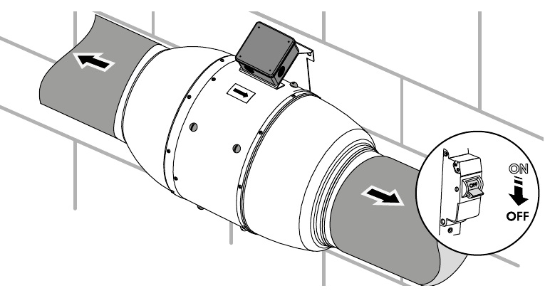
1. Disconnect the power supply and verify that the power is cut off. Disassemble the air duct on both sides of the fan.
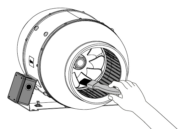
2. Clean the fan with a soft, dry cloth or a brush.
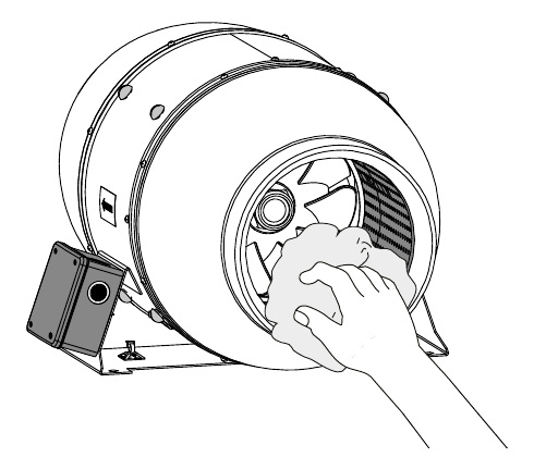
3. Dry the fan surfaces so that they are dry.
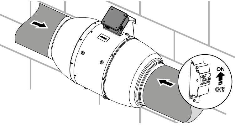
4. Connect an air duct on both sides of the fan.
Connect the power to the fan.
WARNING! Water or liquid must not come into contact with electrical components!
EXAMINATION
Problem:
The fan does not rotate and does not respond to operation, even though the device is connected to the mains power supply.
Possible causes / Remedies:
No power supply. –> Check that the power supply is connected correctly. Fix any connection errors.
Error in internal connection. –> Contact the seller.
Problem:
Low air volume.
Possible causes / Remedies:
The ventilation system is clogged. –> Clean the ventilation system.
Problem:
Increased noise and vibrations.
Possible causes / Remedies:
The fan wheel is clogged. –> Clean the fan wheel.
The fan is not attached sufficiently or is mounted incorrectly. –> Incorrect mounting error.
The ventilation system is clogged. –> Clean the ventilation system.
STORAGE AND TRANSPORT
• Store the device in the manufacturer's original packaging in a dry, sealed and ventilated room at +5 °C to +40 °C and a relative humidity of no more than 70 %%.
• The storage environment must not contain aggressive fumes or chemical mixtures that can cause corrosion or deformation of insulation and seals.
• Use appropriate lifting equipment when handling and storing to avoid damage to the device.
• Follow the handling requirements applicable to the specific type of goods.
• The unit can be transported in the original packaging with all means of transport, provided it is protected from rain and mechanical damage. The unit may only be transported in its operating position.
• Avoid strong shocks, scratches and rough handling during loading and unloading.
• After transport at low temperatures, the unit must be heated to operating temperature for at least 3-4 hours before it is switched on for the first time.
GUARANTEE
DUKA Ventilation provides a 24-month warranty from the date of purchase, in accordance with the Danish Consumer Protection Act. In addition, DUKA Ventilation offers an additional 12-month warranty if all described requirements regarding transport, storage, use, installation, operation, maintenance and warranty provisions are met.
If the unit is installed in a room where there is a risk of mold, the unit must be cleaned particularly thoroughly to remove dust and mold spores. It may be necessary to use a special cleaning agent. Failure to do so will void the warranty.
The warranty does NOT cover:
- The periodic maintenance.
- Device setup, adjustment and disassembly.
The warranty is void if:
- Information regarding transport, storage, use, installation, assembly, operation, maintenance and warranty regulations have not been observed.
• The unit is being used or is situated in an environment for which it was not designed.
- There is damage caused by the effects of mould.
- Visible damage has been applied to the device.
- The device is connected to a different type of power network than described in the manual.
- Damage occurs due to voltage fluctuations in the power grid.
- Technical components have been added or removed in the device.
- Unauthorised repairs have been made to the device.
- The device is faulty due to force majeure (lightning, fire, flood, earthquake, etc.).
- No receipt can be presented for the purchase.
- The warranty has expired.
In the event of a complaint, please fill in our online returns form at: www.dukaventilation.dk/reklamation.
DUKA Ventilation cannot be held liable for warranty obligations performed without prior agreement with DUKA Ventilation.
For other conditions, please refer to Vink Plast's General Terms and Conditions of Sale and Delivery. The latest version can always be found on our website:
www.dukaventilation.dk