


User manual
DUKA S8 Wi-Fi
Wi-Fi enabled extractor fan
heat, humidity and motion sensor
IMPORTANT!
Read and understand the user manual before assembling and using the device.
Inspect the product for damage to the fan, core, front cover, electronic component and external screen. There must be no foreign objects.
as this may damage the device.
The fan is designed for fixed installation and must be connected by an authorised installer.
Save the quick guide so you can always quickly and easily access the latest manual via the QR code.
In the event of the device changing ownership, please pass on the quick guide.
Content
Information and Guarantee
Information and Guarantee
Thank you for choosing a quality fan from Duka Ventilation.
We hope you will be satisfied with your new S8 fan for many years to come.
For your safety, every fan is factory-tested before leaving production.
DUKA S8
The S8 is a multi-function fan that can be installed in bathrooms, living areas (with eight ventilation solutions) or used as an energy-saving heat mover. With the unique function selector, it is simple to change the function. Lift the round front cover and select the function.
Bathroom extractor fan (with eight selectable functions)
S8 has eight selectable functions for ventilation tasks in all residential properties with natural ventilation. It is designed and approved for use in the home's wet rooms (IP44).
Mounted on exterior wall or ceiling (separate and well-insulated duct Ø80 – 125 mm).
Heat transfer – save energy
S8 has a built-in electronic thermostat that controls the fan to move excess heat from, for example, a living room with a wood-burning stove to an adjoining room.
Don't forget the air supply
To achieve good and optimal ventilation in the room, you must also ensure:
– Air supply to the wet room, e.g. via a gap under the door, or another vent/grille.
- Fresh air enters the room, for example via telescopic vents.
Guarantee
DUKA Ventilation provides a 24-month right to make a claim from the date of purchase pursuant to the Sale of Goods Act. In addition, DUKA Ventilation offers a further 36 months
warranty, provided that all described requirements regarding transport, storage, use, installation, operation, maintenance and warranty regulations are met
complied with.
If the device is installed where there is a risk of mould, the device must be cleaned particularly thoroughly to remove dust and fungal spores. This can be
It is necessary to use a special cleaning agent. Failure to do so will invalidate the warranty.
The warranty does NOT cover:
- The periodic maintenance.
- Device setup, adjustment and disassembly.
The warranty is void if:
- Information regarding transport, storage, use, installation, assembly, operation, maintenance and warranty regulations have not been observed.
• The unit is being used or is situated in an environment for which it was not designed.
- There is damage caused by the effects of mould.
- Visible damage has been applied to the device.
- The device is connected to a different type of power network than described in the manual.
- Damage occurs due to voltage fluctuations in the power grid.
- Technical components have been added or removed in the device.
- Unauthorised repairs have been made to the device.
- The device is faulty due to force majeure (lightning, fire, flood, earthquake, etc.).
- No receipt can be presented for the purchase.
- The warranty has expired.
In the event of a complaint, please fill in our online returns form at: www.dukaventilation.dk/reklamation.
DUKA Ventilation cannot be held liable for warranty obligations performed without prior agreement with DUKA Ventilation.
For other conditions, please refer to Vink Plast's General Terms and Conditions of Sale and Delivery. The latest version can always be found on our website:
www.dukaventilation.dk
Contents of the box
• DUKA S8 ventilator
- Mounting kit
• Function setting tool
• Quick guide with QR code to manual
• Ø125 mm pipe connector
• Ø100 mm pipe spigot
Technical Information
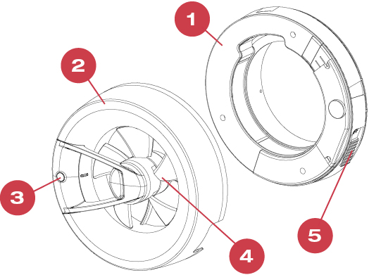
Parts of the fan
1. Frame for electrical connection for ceiling/wall mounting with integrated seals.
2. Removable cover with built-in moisture and heat sensor as well as motor.
3. Movement (IR) and light sensor.
4. Fan part with aerodynamic design that improves
the airflow in the pipework.
5. Built-in switch.
Operating guidelines
The fan must only operate in temperatures from +1 °C to +40 °C.
The fan has an ingress protection rating of IP44 and must not be placed in wet zones. Find out more at sik.dk and in the QuickGuide.
The fan is designed for 230 V AC, 50 Hz. Double insulated, must not be connected to earth.
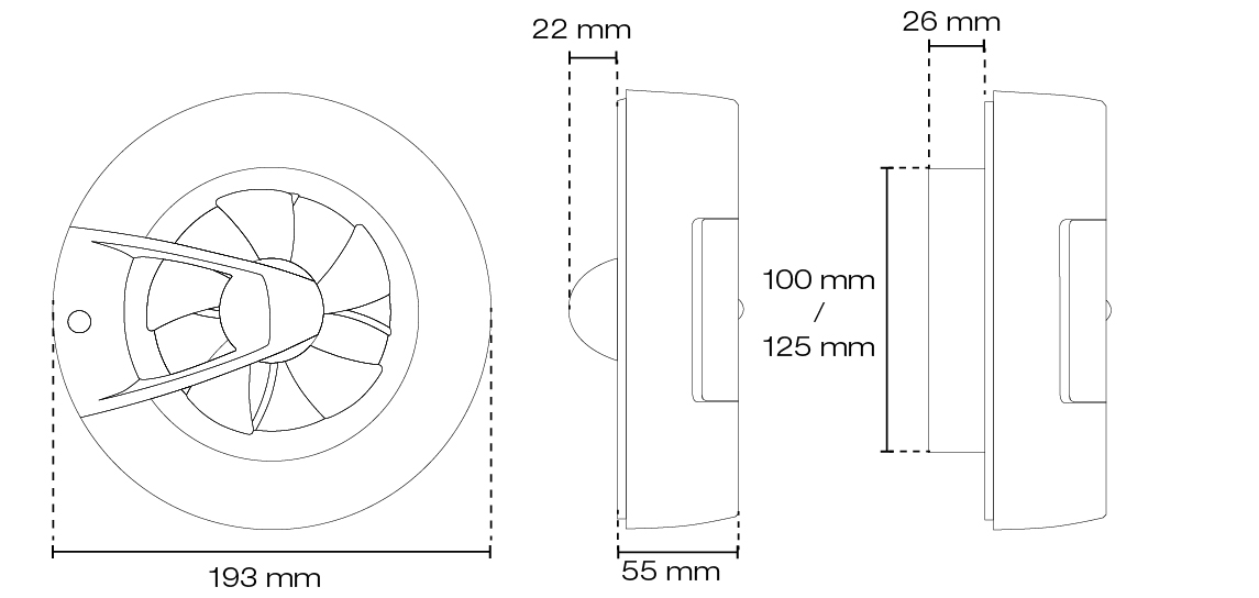
Dimensions
Technical data
Pipe stub [mm] | Ø100 | |||||
Unit voltage [V/Hz] | 100-240 / 50-60 | |||||
IP | IP44 | |||||
Flow rate [m3/h] | 20 | 40 | 60 | 90 | Max | Standby |
Air volume [m3/h] | 20 | 40 | 60 | 90 | 115 | - |
Power consumption [W] | 0,5 | 0,7 | 1,0 | 1,7 | 2,5 | 0,4 |
Current [A] | 0,018 | 0,019 | 0,021 | 0,029 | 0,038 | 0,017 |
Air flow rate [l/s] | 6 | 11 | 17 | 25 | 32 | - |
SFP [W/l/s] | 0,07 | 0,05 | 0,05 | 0,06 | 0,08 | - |
Sound level at 3 m | 9 | 13 | 18 | 22 | 27 | - |
Installation
NOTE: The fan is intended for fixed installation and must be connected by an authorised electrician.
Preparations
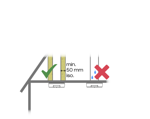
Ensure that the pipework is insulated. If it is not insulated with at least 50 mm of insulation, the following may occur:
condensation that can drip down into the extractor fan and cause a short circuit.
Placement of ventilator
The fan must be installed in accordance with the applicable regulations for electrical installations in wet rooms. Find out more at SIK.dk
and the QuickGuide.
Wiring
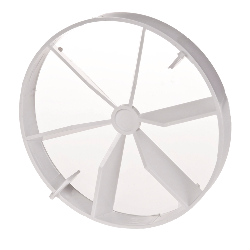
The fan is fitted to the outside of the wall or ceiling. A shut-off damper can only be fitted if the fan is wall-mounted.
Suitable for duct size Ø100 mm.
1. Switch off the power
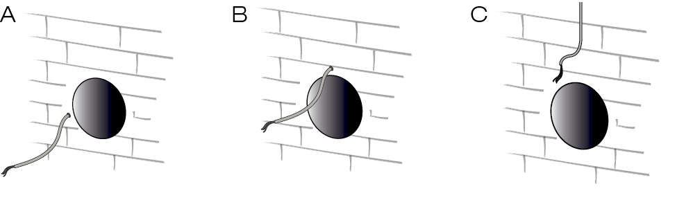
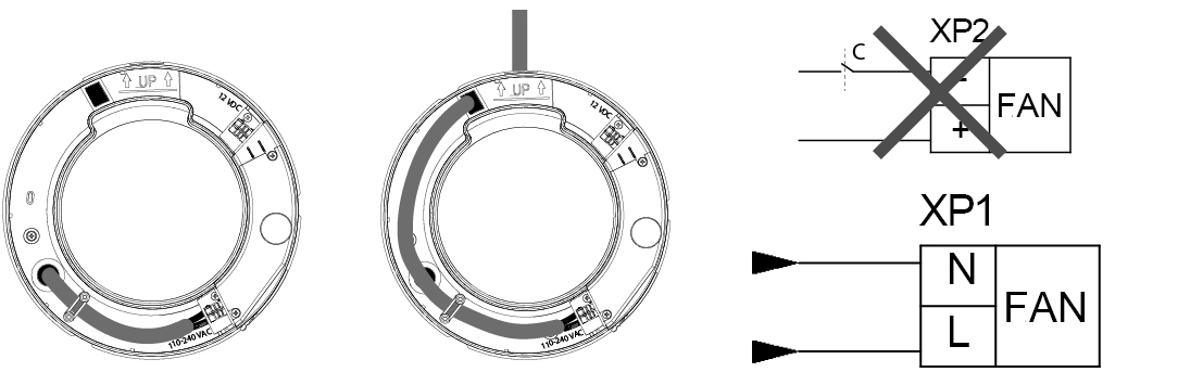
2. If the cabling for the unit is to be concealed in the wall, it can emerge in positions A and B.
If necessary, use the template provided to position the wiring
If the cable is routed along the outside of the wall, it must be fed through the hole as shown in C.
Shut-off damper for the S8 fan
Preparing fan
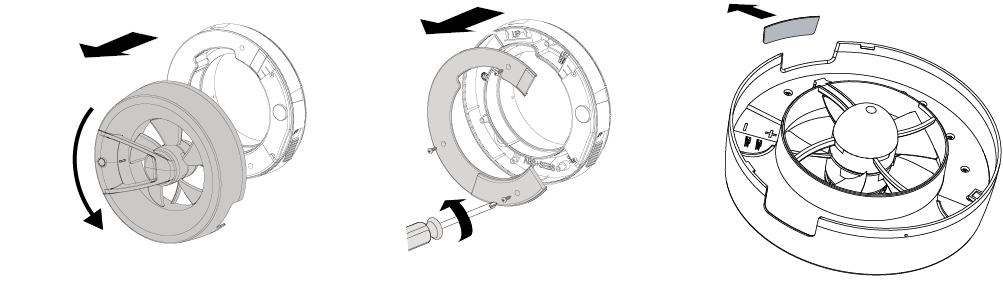
The motor unit has a bayonet fitting, which makes it easy to set up and clean.
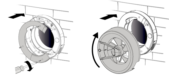
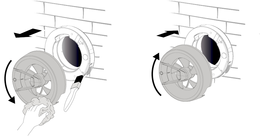
1. Grasp the front and turn anti-clockwise. Lift the motor unit off the wall bracket.
2. The cover of the wall frame is held in place by 3 screws (PH1). Loosen the screws and remove the cover.
3. If the cable is to be routed through the top of the front panel, a hole must be made in the front panel for the cable. Here, a thinner section has been cut out of the cover so that
is cut off. Use the square piece in the cardboard template to mark out the cutout for the best result.
Assembly of the wall frame
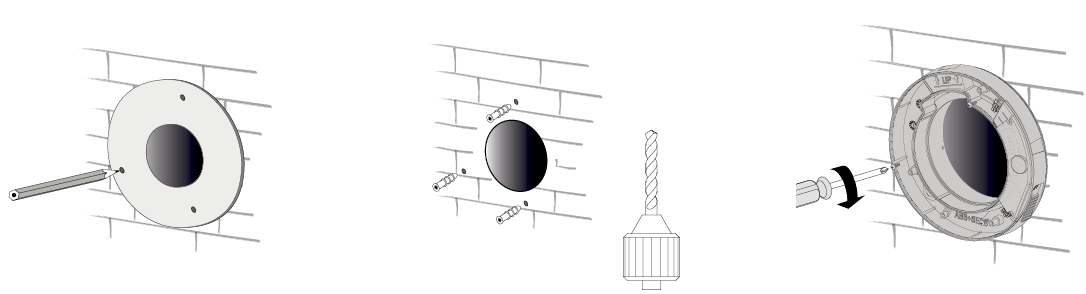
1. Mark the holes using the supplied template.
Drill holes and insert wall plugs into the holes
3. Screw the wall frame firmly to the surface (PH2 x3). Ensure the ”UP” marking points upwards for wall mounting.
Electrical connection
Please note! Must be connected by a qualified installer. For all electrical work on the fan, the power supply must be disconnected.
The fan is designed for 230 V AC, 50 Hz. Double insulated, must not be connected to earth.
1. Run the cable to the XP1 junction box
– The fan can also be connected to 12V via the XP2 connector. Do not connect power to both.
Seals
To prevent water from entering the engine, the partition frame has several integrated seals (seal with silicone, for example, if necessary):
1. On the reverse side, seal against the substrate.
2. At the cable entry point.
3. At the screw bushings (3 in total). Note: Any gap between the bushing and the ventilation pipe must be sealed.
Fit cover and front
1. Screw the lid on
2. Fit the front and turn clockwise until the front is locked in the bayonet fitting.
3. Switch on the power
Switch
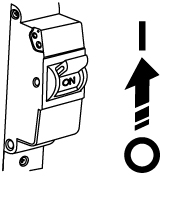
The fan is delivered switched off with the switch so that ”OFF” is visible. The fan is activated by sliding the switch so that ”ON” can be seen.
According to the EN 60335-1 standard, the fan must be capable of
disconnected from the mains electricity supply. This is fulfilled by the built-in
switch (2-pole, 3 mm contact gap).
Functions and features
DUKA S8 has 8 functions which are created from the 4 available built-in sensors. Not all sensors are active at all times. See which functions are available
activated in every function in the next section. Functions 1-4 include background ventilation and are the recommended functions for a bathroom.
The built-in sensors are:
– Humidity sensor that sends a signal to the device when there is a major change in relative humidity.
– Temperature sensor that sends a signal to the device when the room temperature reaches 28°C, and turns off again when the room reaches 24°C.
– Motion sensor that sends a signal when there is movement in front of the device.
– A light sensor that sends a signal to the device when there is a sudden change in the light levels in the room.
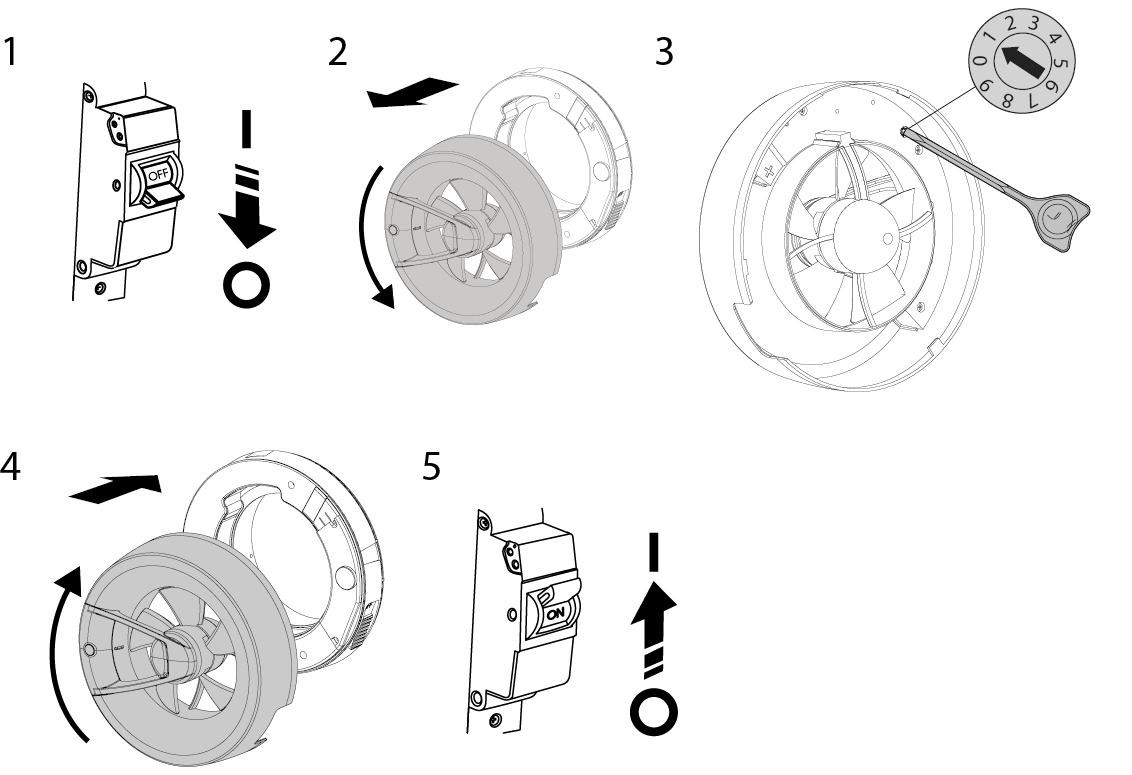
The functions are selected using the position button located on the inside of the front panel.
Remove the front as indicated in the drawing and turn the position knob using the dedicated tool supplied with the unit.
Job descriptions
Features with background ventilation
Function 1: Low-level basic ventilation with motion and humidity control
The fan operates at a basic ventilation rate of 20 m³/h.
If the motion or light sensor is triggered, the fan switches to
60 m³/h with a delay of 30 seconds.
When there is no longer a signal from the motion or light sensor, the following will occur:
The fan will continue to run at a rate of 60 m³/h for 15 minutes.
If the humidity sensor is triggered, the fan switches to 90 m³/h. If the humidity falls
If the humidity rises again, switch the fan back to basic ventilation at 20 m³/h
unless there is still a signal from one of the other sensors. In that
In this case, the sensors will take over and the fan will run at 60 m³/h
with a 15-minute cool-down.
Function 2: Background ventilation with motion and humidity control
The fan operates at a basic ventilation rate of 40 m³/h.
If the motion or light sensor is triggered, the fan switches to
60 m³/h with a delay of 30 seconds.
When there is no longer a signal from the motion or light sensor, the following will occur:
The fan will continue to run at a rate of 60 m³/h for 15 minutes.
If the humidity sensor is triggered, the fan switches to 90 m³/h. If the humidity falls
the humidity has changed the fan back to baseline ventilation 40 m3/h
unless there is still a signal from one of the other sensors. In that
In this case, the sensors will take over and the fan will run at 60 m³/h
with a 15-minute cool-down.
Function 3: Basic ventilation with humidity control
The fan operates at a basic ventilation rate of 40 m³/h.
If the humidity sensor is triggered, the fan switches to 115 m³/h. If the humidity falls
Once the humidity has returned to normal, switch the fan back to basic ventilation 40
m³/h. Signals from other sensors are ignored.
Function 4: High basic ventilation with humidity control
The fan operates at a basic ventilation rate of 60 m³/h.
If the humidity sensor is triggered, the fan switches to 115 m³/h. If the humidity falls
Once the humidity has returned to normal, switch the fan back to basic ventilation 40
m³/h. Signals from other sensors are ignored.
Functions with standby
Function 5: Standby mode with motion and humidity control
The fan remains stationary in standby mode until it receives a signal from a sensor.
If the motion or light sensor is triggered, the fan switches to
60 m³/h with a delay of 30 seconds.
When there is no longer a signal from the motion or light sensor, the following will occur:
The fan will continue to run at a rate of 60 m³/h for 15 minutes.
If the humidity sensor is triggered, the fan switches to 90 m³/h. If the humidity falls
The humidity switches the fan off in standby mode unless there is still
is a signal from one of the other sensors. In that case, those sensors
switch on and the fan will run at 60 m³/h for 15 minutes
chase.
Function 6: Standby mode with motion and humidity control + ventilation for 30 minutes every 12 hours
The fan remains stationary in standby mode until it receives a signal from a sensor.
If the fan has not received a signal for 24 hours, the fan will run
at a rate of 20 m³/h for 30 minutes every 12 hours until it receives a signal from a sensor.
If the fan receives a signal from one of the sensors, it will run as
Function 5.
Function 7: The fan remains stationary in standby mode until it receives a signal from a sensor.
If the temperature sensor is activated, the fan switches to 90 m³/h, and
stops again when it no longer receives a signal from the sensor.
The temperature sensor starts when the temperature reaches 28°C and stops
Yes, at 24°C.
Function 8: Standby mode with humidity control
The fan remains stationary in standby mode until it receives a signal from a sensor.
If the humidity sensor is triggered, the fan switches to 115 m³/h. If the humidity falls
the humidity has switched the fan back to standby mode.
Maintenance
The fan must be maintained at least once every 6 months.
Maintenance steps:
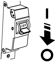
• Set the fan switch to ”OFF”, and ensure that the power supply is switched off.
• Remove the front panel and wipe the fan parts with a dry cloth and/or a soft brush.
• Reinstall the front panel on the cooker hood.
• Switch on the power to the fan and set the switch to ”ON”.
NOTE: Ensure that water or other liquids do not come into contact with the electrical components.
Troubleshooting
Problem | Possible cause | Solution |
When the unit is connected to the power supply, the fan does not rotate and does not respond to any controls. | No power supply | Ensure the power supply is correctly connected. If not, troubleshoot the connection error. |
The fan is set to ”do not disturb” mode | Connect to the fan and set the mode. | |
Internal connection error | contact DUKA Ventilation at: www.dukaventilation.dk/reklamation | |
Low airflow | The ventilation system is blocked. | Clean the ventilation system. |
No supply air | Ensure the extractor fan receives supply air from a vent in the window, door, ceiling or wall. | |
Increased noise or vibration | The fan is clogged | Clean the fan. See more under ”maintenance” |
The fan is not securely fastened or is incorrectly fitted. | Troubleshoot the installation error. | |
The ventilation system is blocked. | Clean the ventilation system. | |
The fan's sensor is not responding | Internal sensor error. | Reset the device in the app. |