


User manual
SmartFan
Extractor fan with humidity and timer control
Content
DUKA SMARTFAN
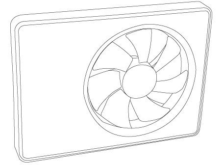
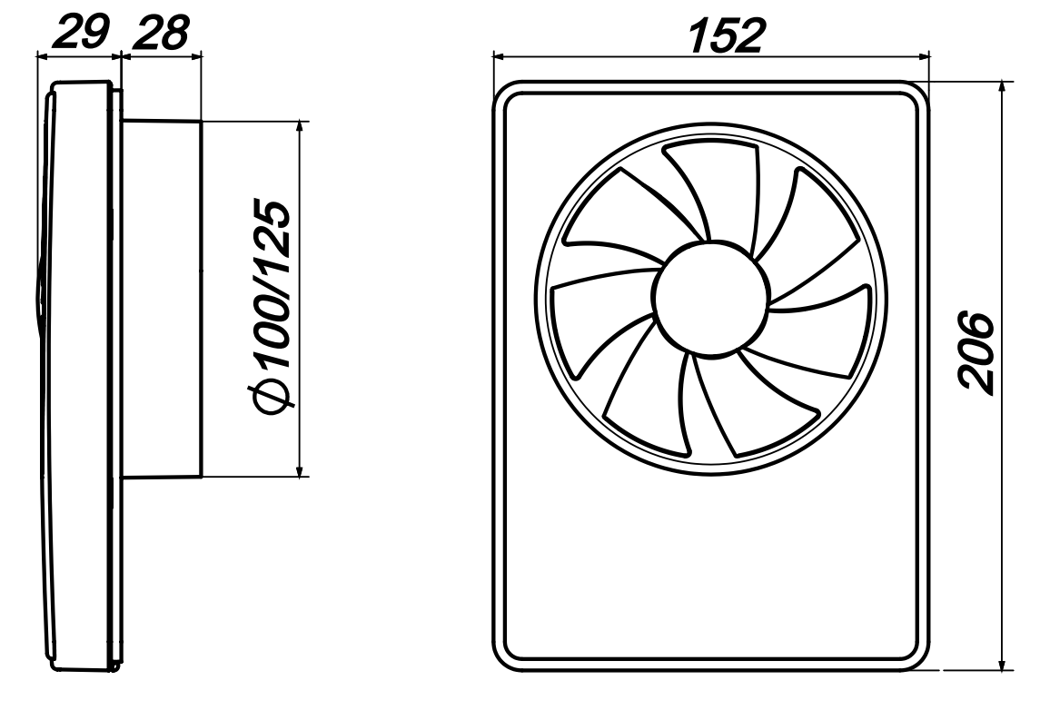
The SmartFan has a flat design with a shallow installation depth, which is optimal for tight installation conditions. The ventilator can be connected to both Ø100 and Ø125 mm ducts using the supplied spigots.
This user manual contains a technical description, user and service manual as well as technical data and an installation guide for the DUKA SmartFan extractor fan.
Please read these instructions thoroughly before installation and use.
The installation must comply with the building regulations.
DUKA Ventilation reserves the right to make changes to the technical data, design and configuration of the product in order to incorporate the latest technical developments. The most up-to-date documentation can always be found at www.dukaventilation.dk.
Important before installation
Before installation, service and maintenance, the power supply to the fan must be disconnected.
The fan is intended for fixed installation and must therefore be connected by an authorised installer.
The single-phase electricity grid must comply with applicable electrical codes and standards.
The installation must be equipped with an automatic circuit breaker.
The device must be connected to the mains power supply via a miniature circuit breaker (MCB) integrated into the fixed wiring.
Check the unit for visible damage to the fan and casing before starting installation. The internal parts of the casing must be free of foreign bodies that could damage the fan components.
Avoid applying pressure to the fan during installation. Damage to the casing can lead to motor failure and noisy operation. Incorrect use and unauthorised modifications are not permitted and will invalidate the warranty.
Ensure that smoke, carbon monoxide and other combustion gases cannot enter the room through open flue ways or other fire safety systems. Adequate air supply must be ensured for proper combustion and extraction of gases through the chimney to prevent downdraughts. Conveyed air must not contain dust or other solid material with impurities, sticky substances or fibrous materials.
Must not be used in explosive or hazardous environments with alcohol, fuel, spray agents, etc.
Air inlets and outlets must not be blocked to ensure optimal airflow.
Contents of the box
Ventilator 1 pc.
100 mm pipe spigot 1 pc.
125 mm spigot pipe 1 pc.
Screws and rawlplugs 4 pcs.
User manual 1 pc.
Technical data
The DUKA Smart Fan extractor is an axial fan made of high-quality plastic designed for extraction.
Voltage [V] 100–240
Frequency [Hz] 50–60
Max. Power [W] 3.0
Max. air volume [m3/h] 133
IP rating IP44
Stud diameter | Speed and speed | Max current
[W] | Air volume [m3/h] | Sound level at 3 m [dBA] |
Ø100 mm | Step 1 | 2,3 | 74 | 20 |
Step 2 | 2,9 | 92 | 28 | |
Ø125 mm | Step 1 | 2,3 | 90 | 21 |
Step 2 | 3,0 | 108 | 29 |
IP44 rating protects against access to hazardous parts and the device against splashing water.
The fan can be used in rooms with a room temperature from +1 ºC to +45 ºC
The fan is classified as a Class II electrical appliance.
Dimensions
Assembly
1. For vertical installation, the fan must be protected against the accumulation of water and condensation in the ductwork. Installation directly with a vertical exhaust air outlet is not permitted. For ceiling installation, the non-return flap must be removed.
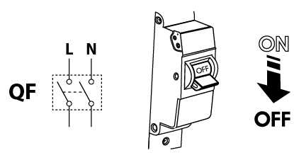
2. Disconnect all power supplies before carrying out the installation.

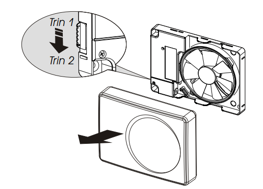
3. Remove the front panel of the extractor fan.
4. Mark the holes for mounting and cable routing.
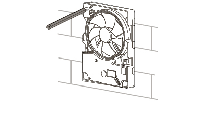
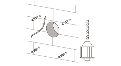
5. Route the power cable to the ventilation duct. Drill holes for mounting and fit wall plugs.
6. Secure the fan to the wall with the screws.
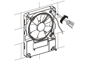
7. Remove the cover to access the terminal block and connect the power cable to the fan according to the electrical diagram (see below). Reassemble the fan in reverse order.
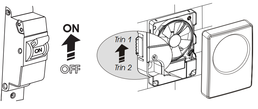
8. Switch on the power at the isolator switch. Choose whether the fan should ventilate on speed 1 or speed 2.
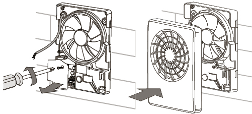
El diagram

The fan starts automatically when the humidity exceeds the set level. It can also be activated manually by turning on the switch.
When the switch is turned off, or the humidity falls below the set level, the fan continues to run for the selected overrun time of 2–30 minutes.
If the fan is only to run on the humidity sensor, it must be connected with a permanent live L and neutral N.
Timer and humidity sensor
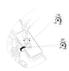
T: Adjusting the clock
Can be set from 2 to 30 minutes.
Increase: Turn the T knob clockwise (to the right)
Lower: Turn the T knob anti-clockwise (to the left)
H: Humidity adjustment
Can be adjusted from 60% to 90%.
Increase: To increase the humidity, turn the H knob clockwise (to the right)
Reduce: To lower the humidity, turn the H knob anti-clockwise (to the left)
WARNING
When adjusting the timer, the power to the fan MUST be switched off. Use a very small screwdriver to adjust these two settings. Take care not to tighten them too much.
The factory setting is 75% humidity + 2-minute run-on time
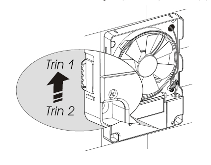
The fan can operate at two different speeds. The speed is adjusted using the slide switch on the side of the housing.
Technical maintenance
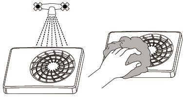
Maintenance involves regularly cleaning the surface of the fan. A soft, damp cloth with a mild soapy solution should be used.
Wipe the surface with a dry, soft cloth. Avoid getting water on the motor and circuit board.
Switch off the power to the fan.
1. Remove the front panel.
2. Clean the front panel. Wipe the front until it is dry again.
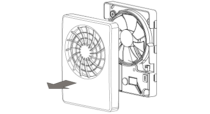
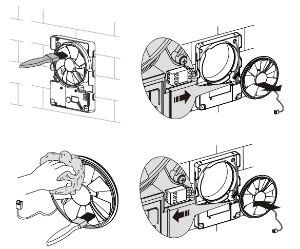
3. Clean the fan blades with a dry, soft cloth or brush. The fan blades can be removed for easier cleaning.
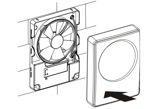
4. Fit the front panel and switch on the power to the fan.
Transport and storage
Store the fan in its original packaging in a dry, well-ventilated room at a temperature of between +5 ºC and +40 ºC and a relative humidity of up to 70 %.
The storage room must not contain aggressive and chemical vapours.
The fan must not be subjected to continuous pressure and load.
PLEASE NOTE: All electrical work must be carried out by a registered electrician.
The fan may be transported by any vehicle, provided that it is protected against damage during transport and the elements.
The fan must be protected against knocks and impacts throughout the entire journey
Warranty terms
DUKA Ventilation offers a 24-month warranty from the date of purchase, in accordance with the Sale of Goods Act.
In addition, DUKA Ventilation offers a further 36-month warranty on top of the right to make a claim, provided that all the obligations and instructions set out regarding use, installation, storage, transport and maintenance are complied with.
In the event of a complaint, please present your receipt and, if applicable, the installation invoice from the electrician. The fan must be used as described in the user manual.
The warranty does NOT cover:
• Routine maintenance.
• Fitting and removing the fan.
• Fan installation.
Please contact your dealer or installer for warranty service. DUKA Ventilation cannot be held liable for warranty work carried out without prior agreement with us or our dealer.
The warranty does not cover the following cases:
• If the fan has not been installed in accordance with the installation instructions, this also includes parts within the fan.
• If all electrical connections have not been made correctly and in accordance with the manual.
• If the fan has not been properly serviced at regular intervals.
• If there is visible damage to the fan housing or to any parts inside the housing.
• If any technical components have been added to or removed from the fan.
• In the event of incorrect use of the fan.
• Deviation from the user manual.
• Connection to an electricity supply other than that described in the manual, i.e. the standard mains supply.
• Fluctuations in the mains voltage.
• Unauthorised repairs to the fan.
• If the warranty has expired.
• Derogation from transport rules.
• Deviation from storage regulations.
• Fan faults caused by Force Majeure. (fire, flood, earthquake, rough handling)
• If a receipt for the purchase cannot be provided.